








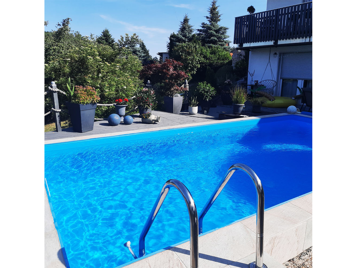
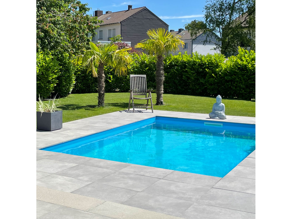
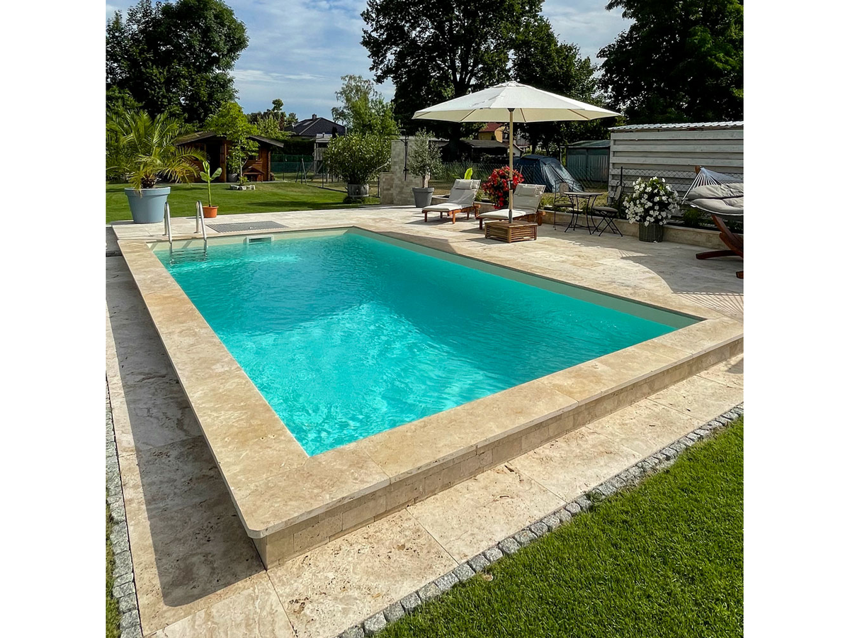
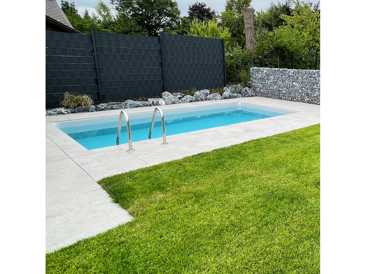
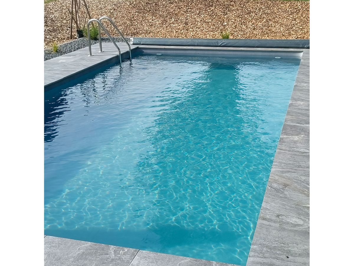
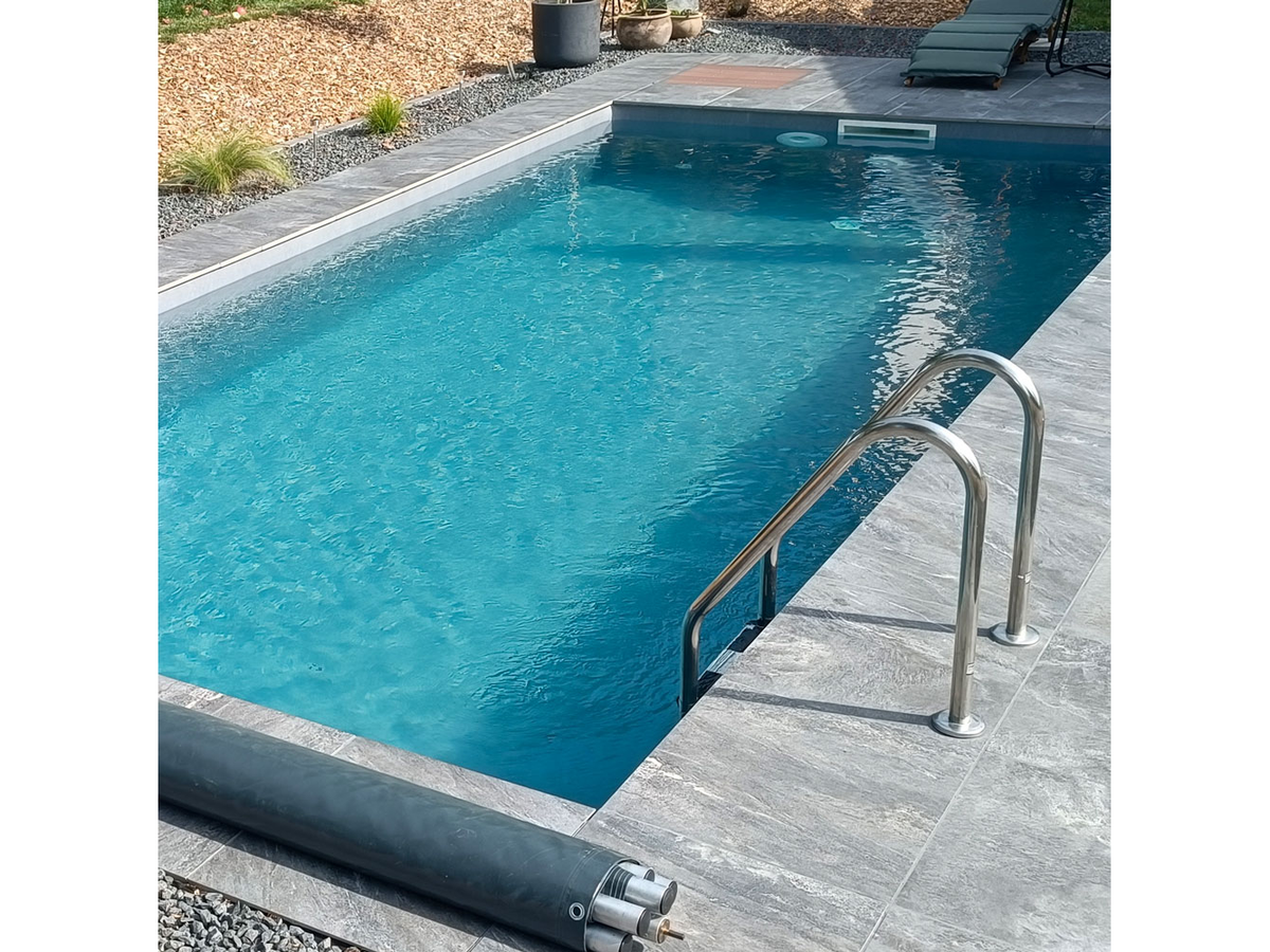
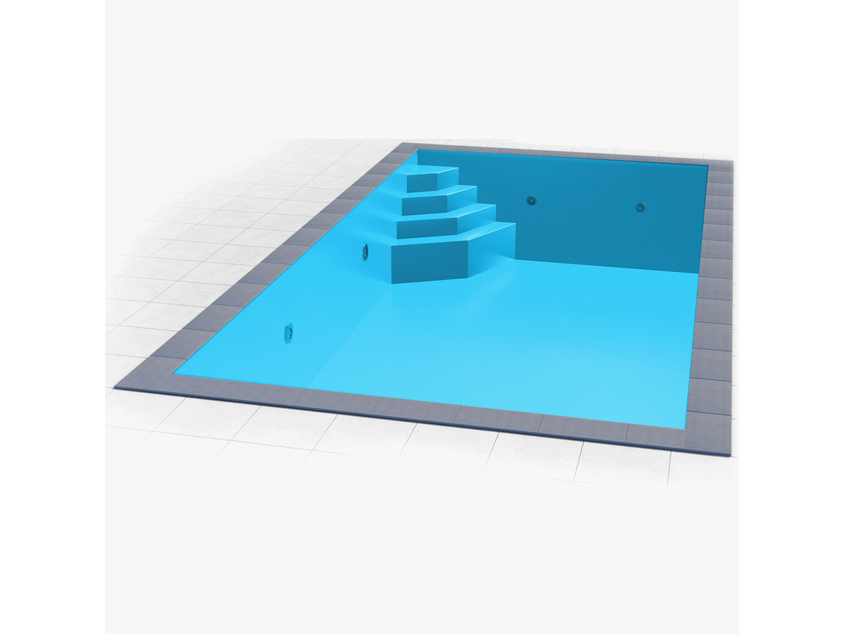

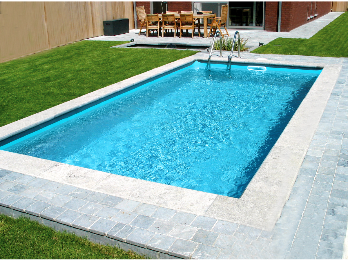
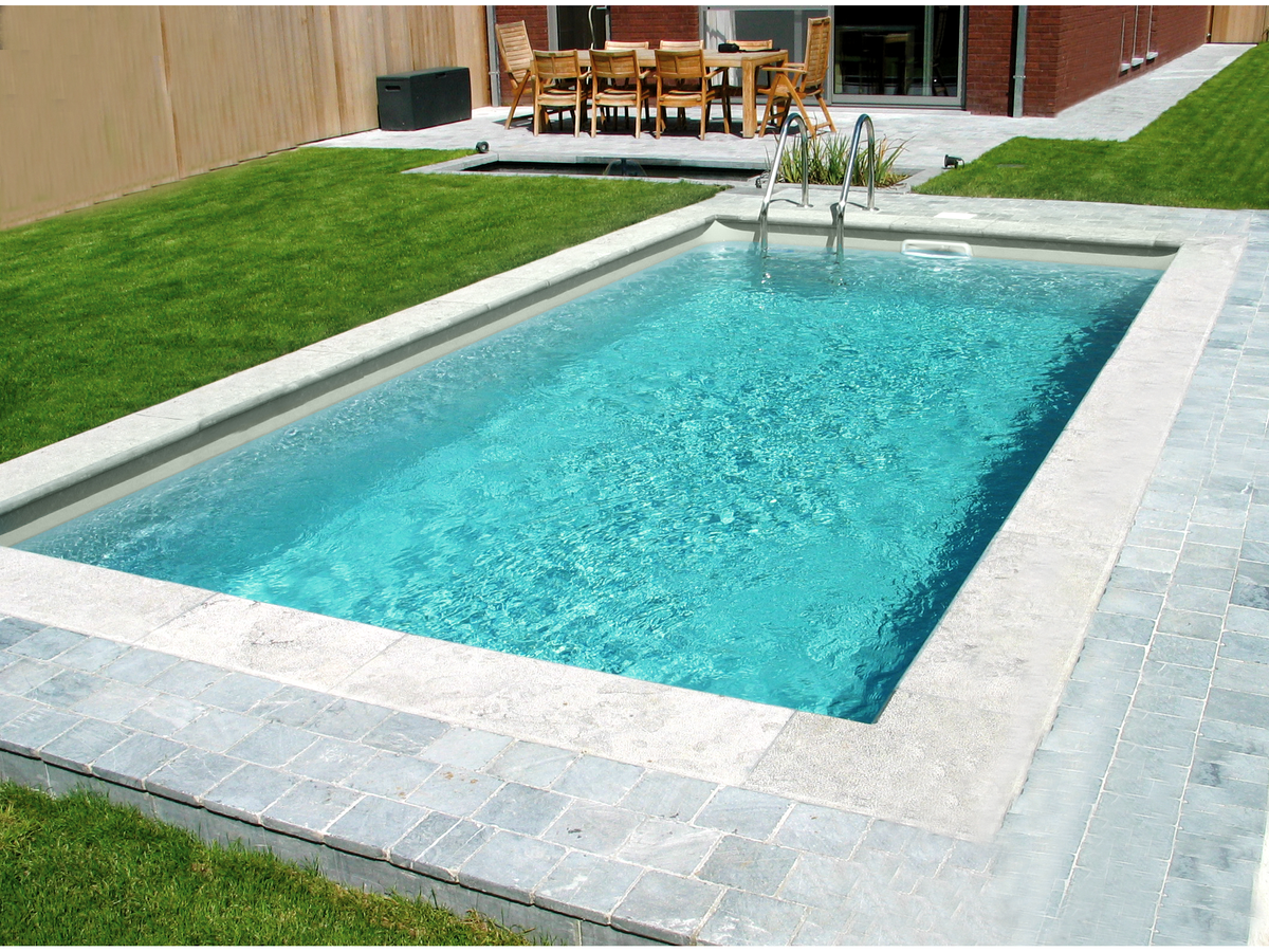
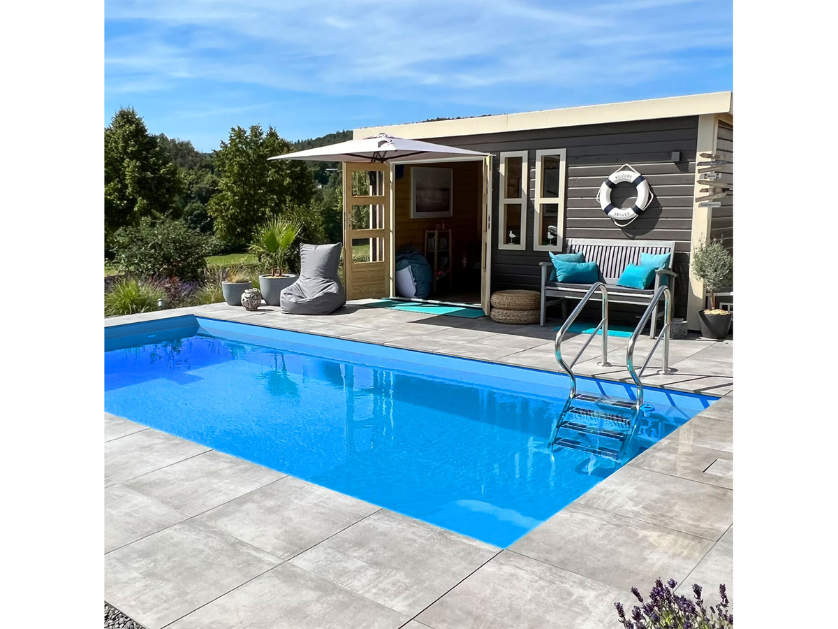
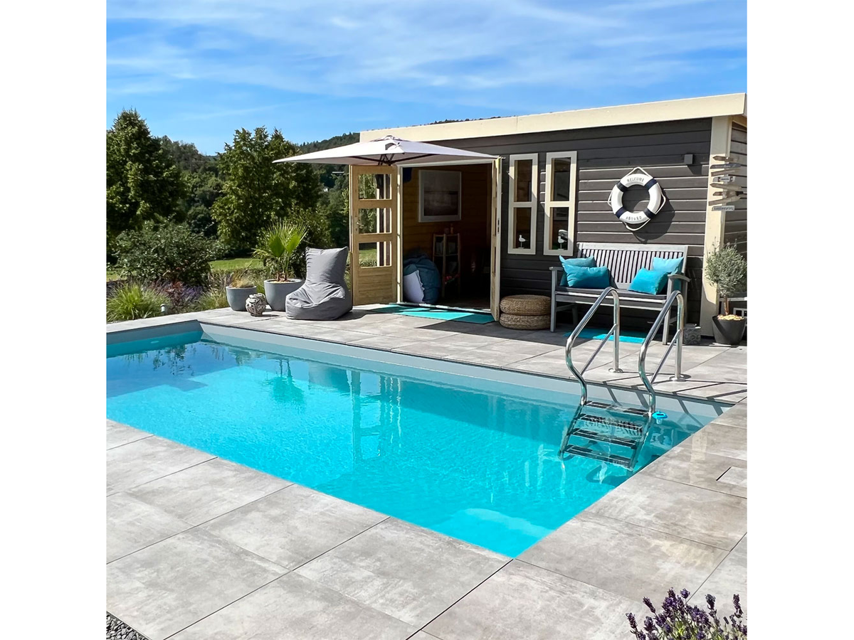
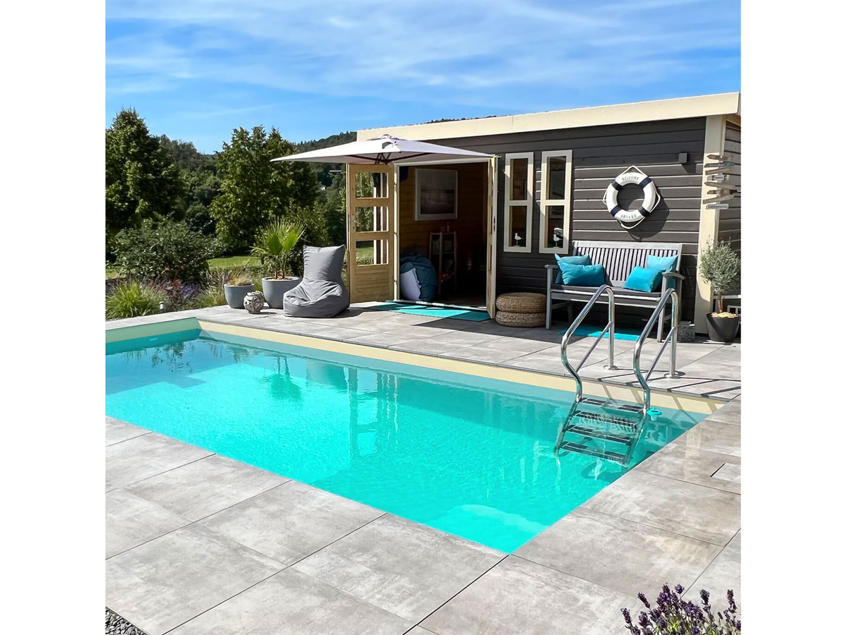
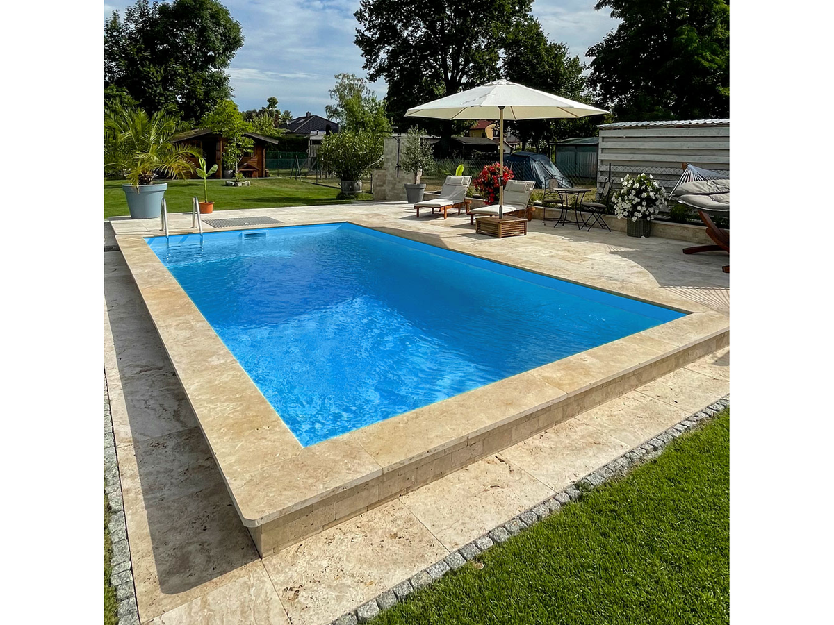
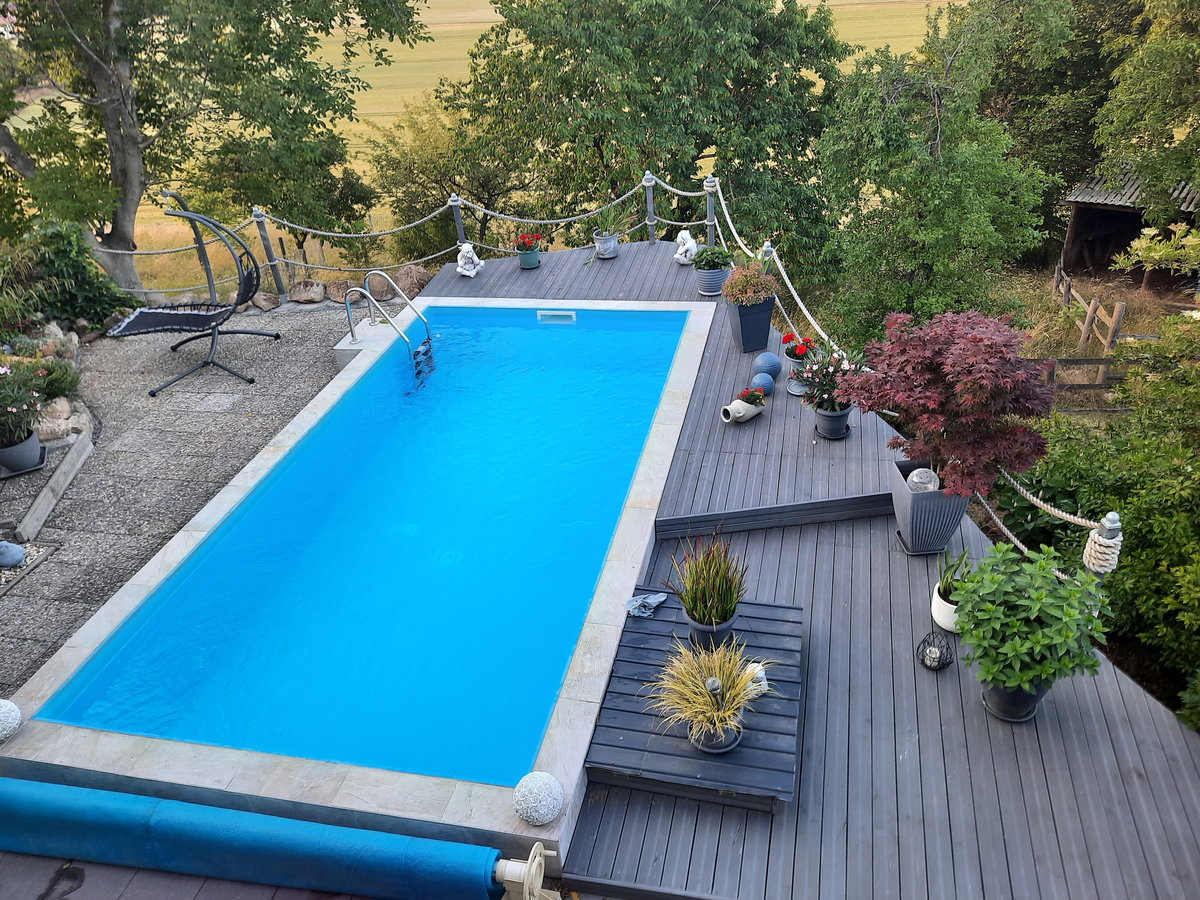
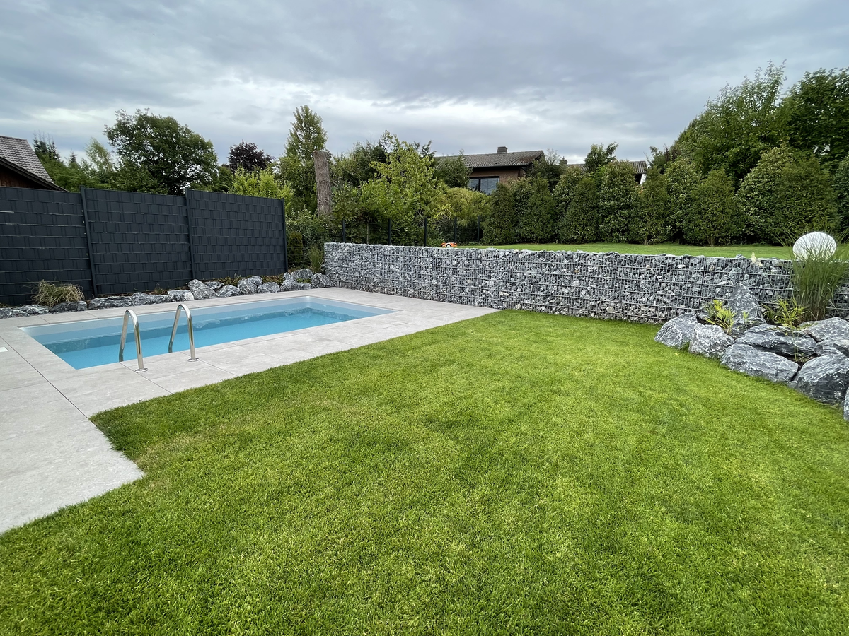
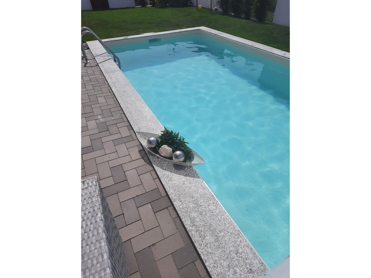
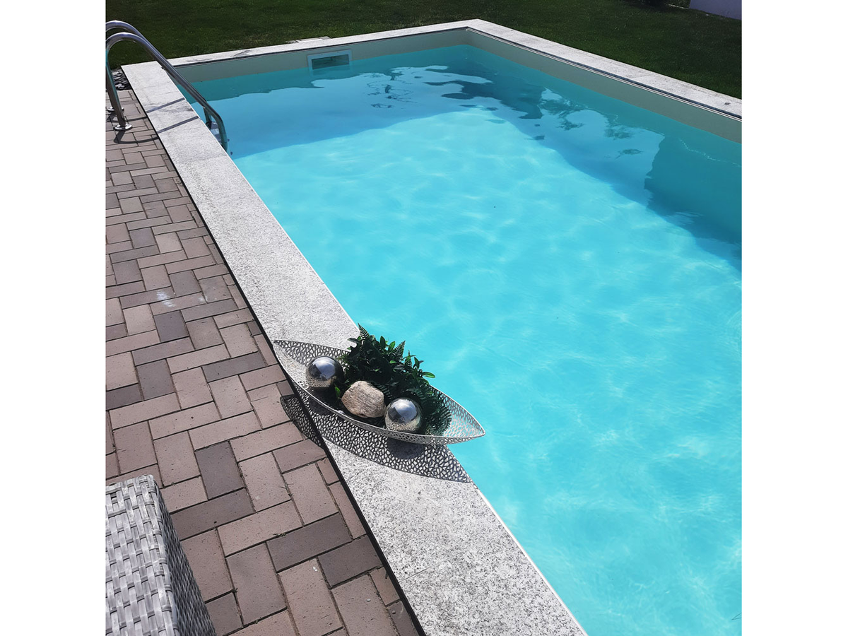
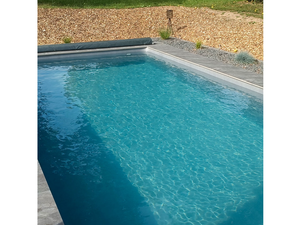
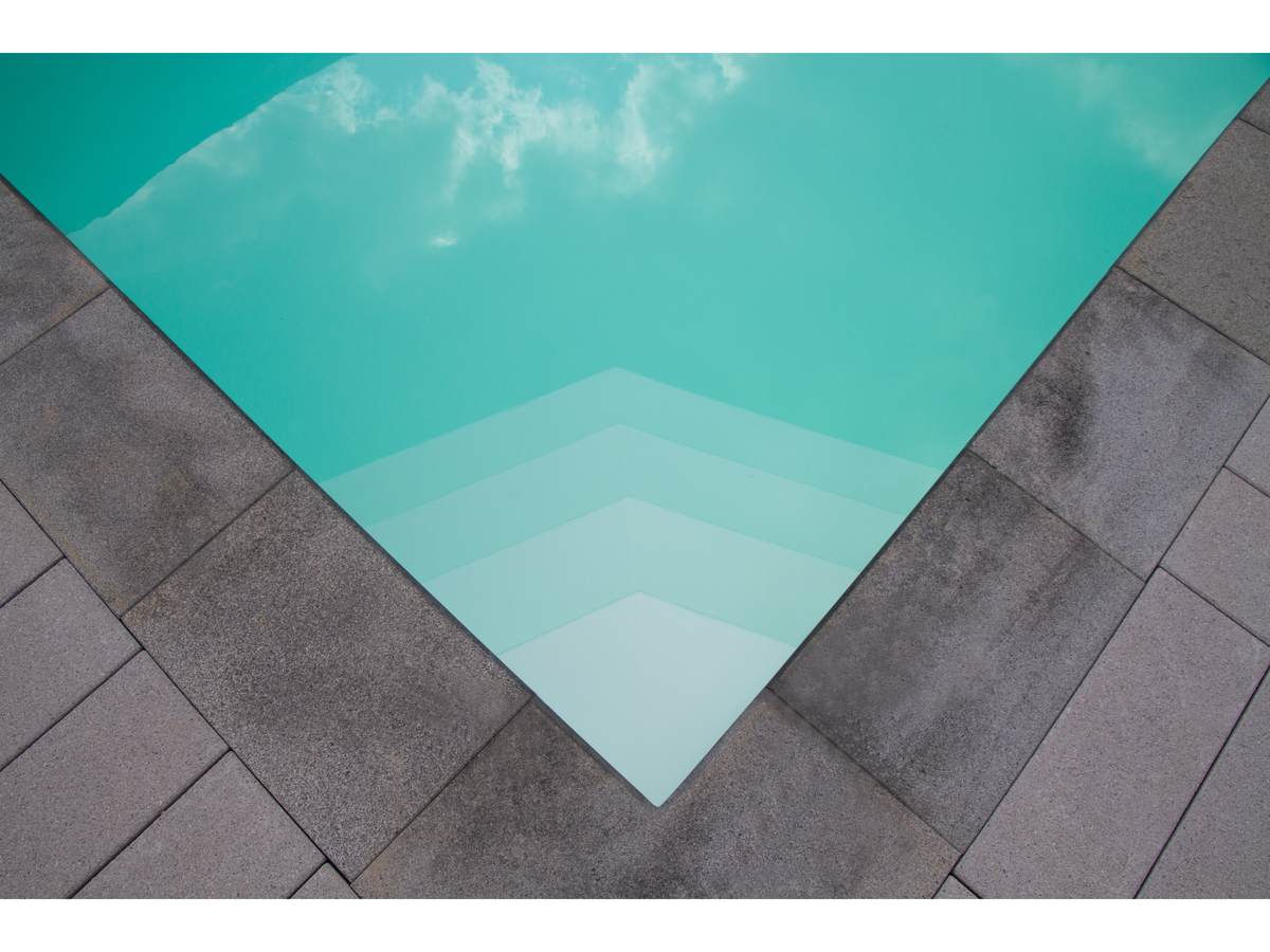
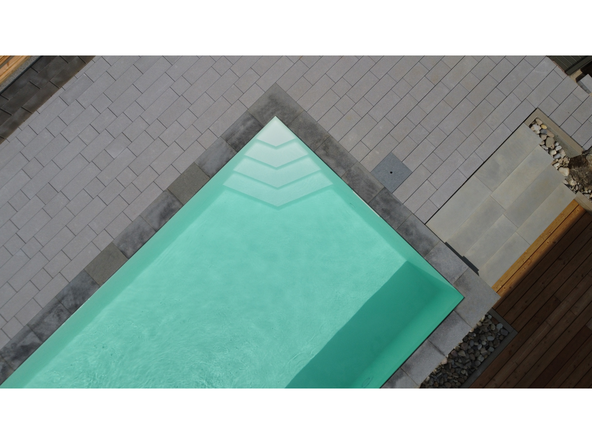
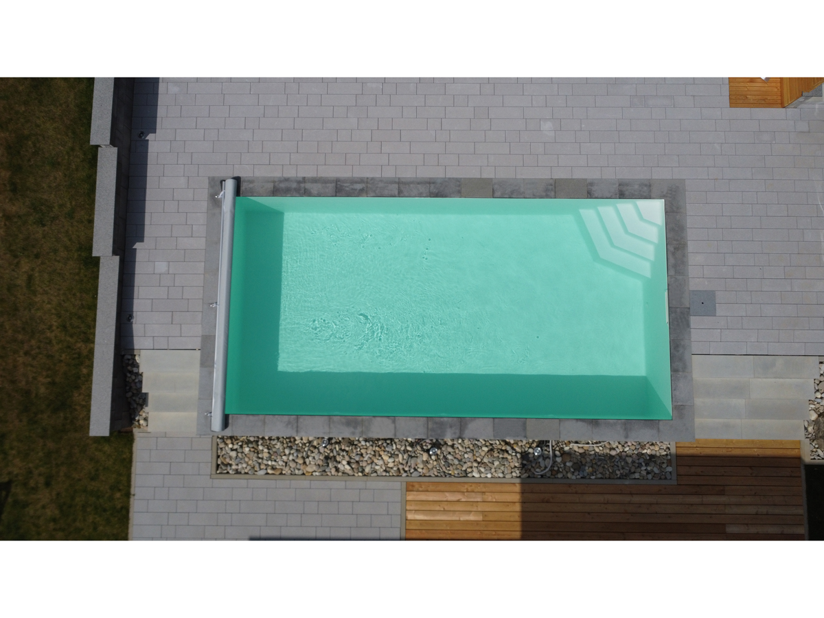
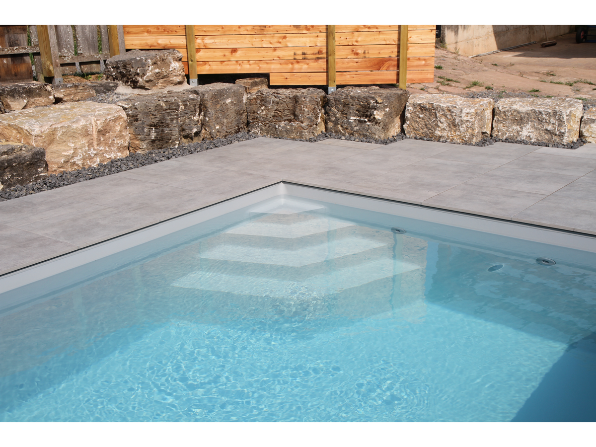
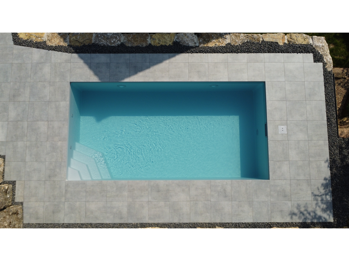
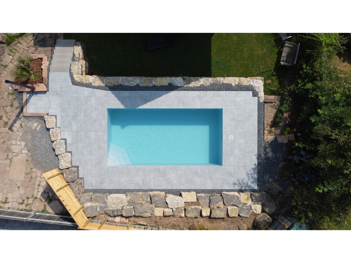
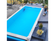
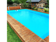
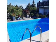
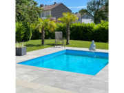
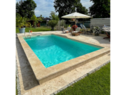
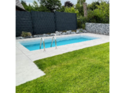
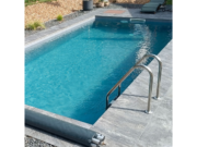


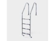
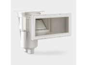
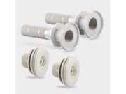
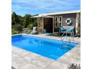
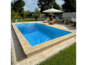
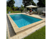
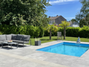
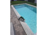
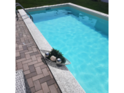
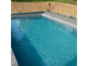

Rectangular EPS pool Poolsana Linea 4 DL 8×4 m – PROFI package
Price range: €6070.00 through €10140.00 incl. VAT
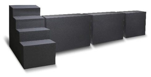
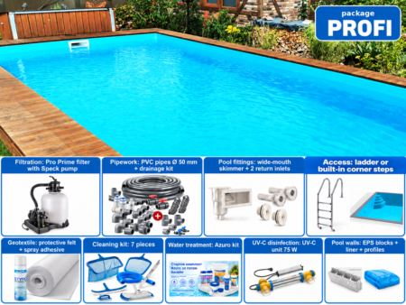
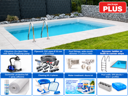
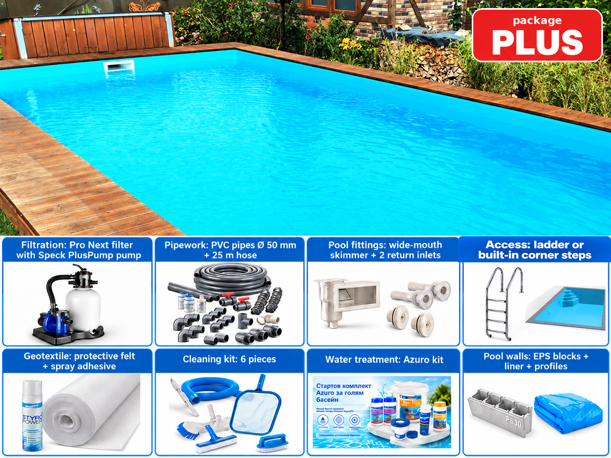
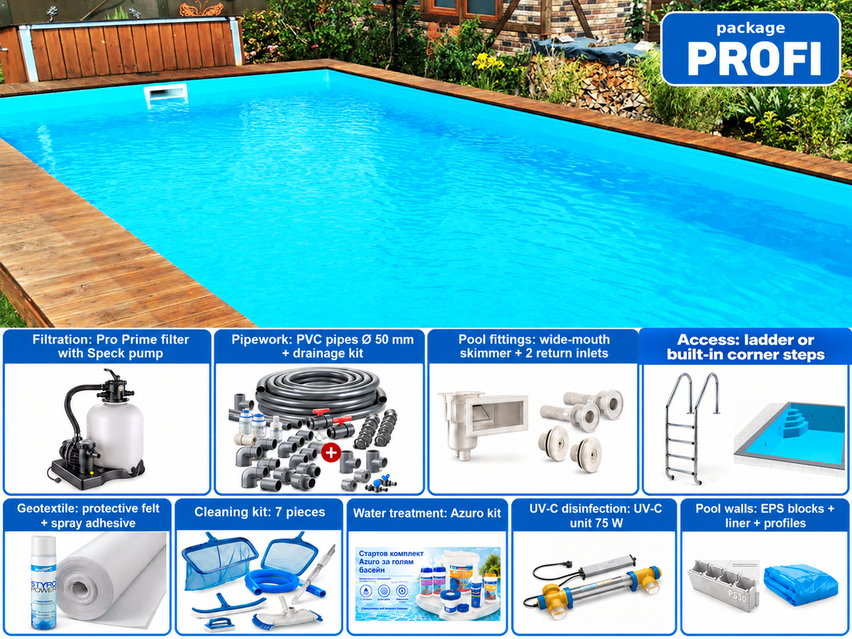
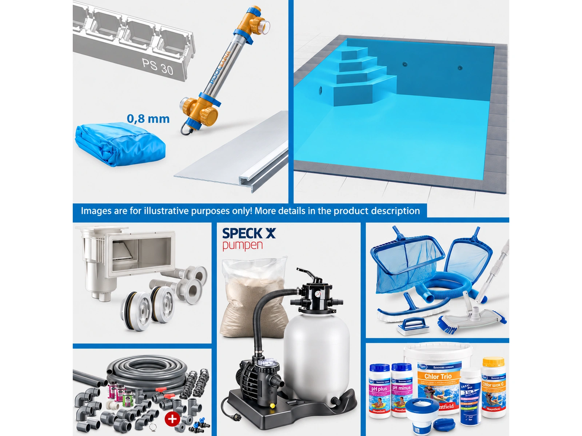
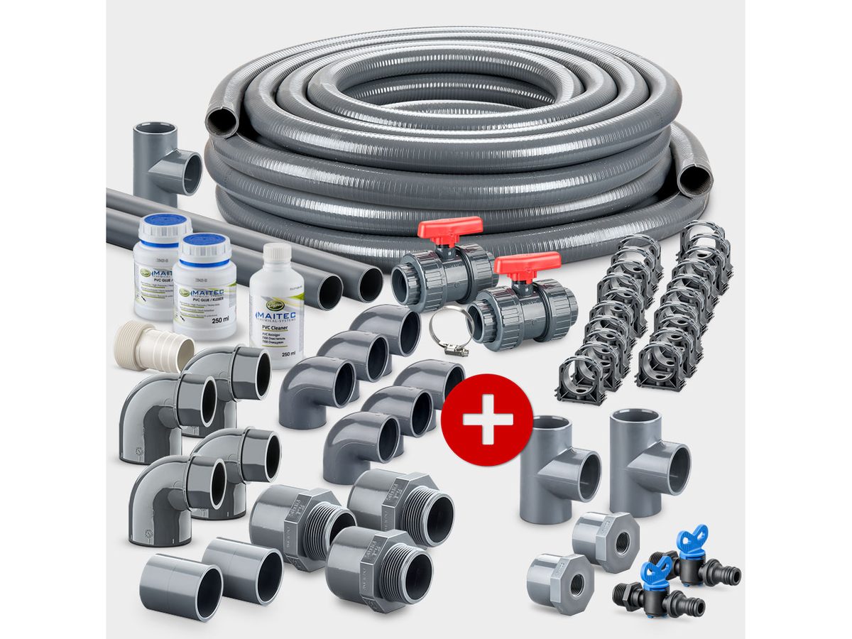
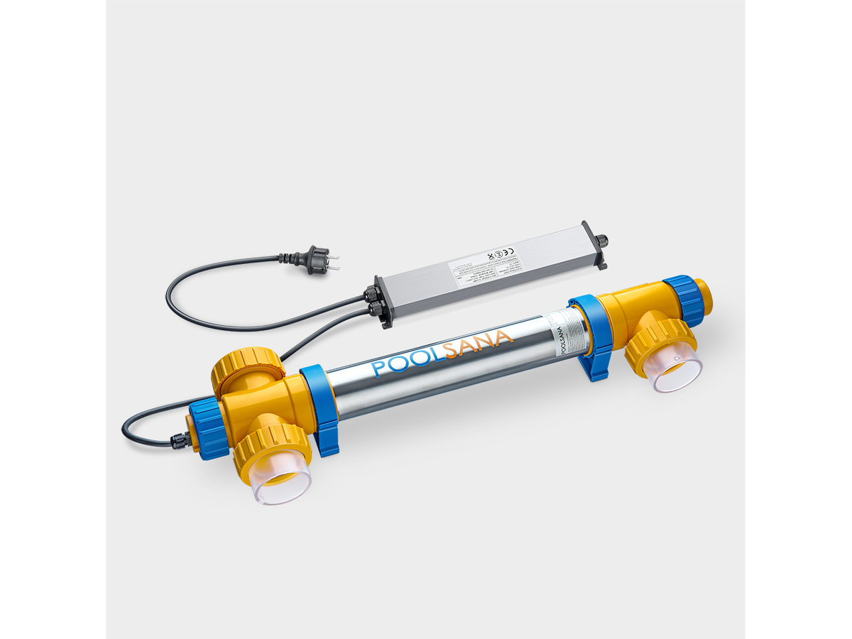
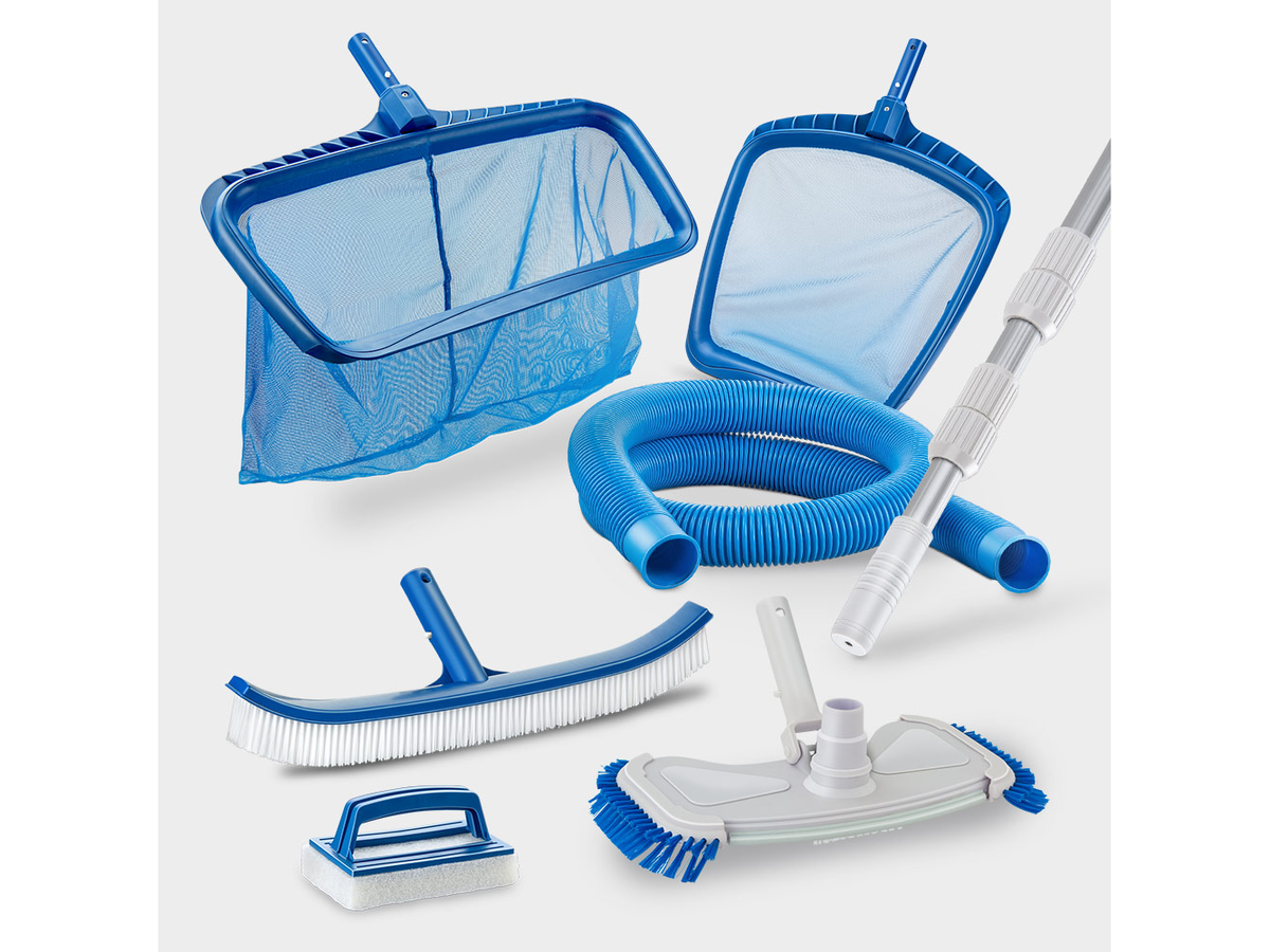
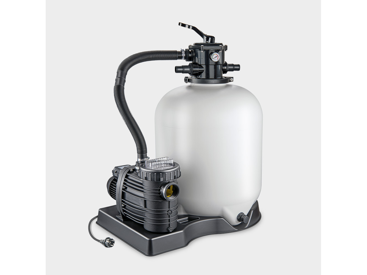
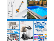
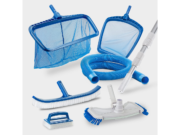
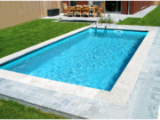
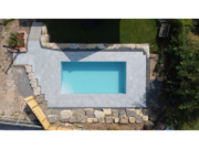
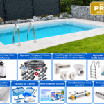
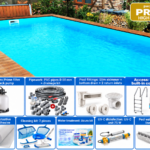
The 8×4 m PROFI polystyrene pool is a complete kit for an in-ground 8.00 × 4.00 m pool with a depth of 1.50 m. The walls are made of 125 lightweight EPS blocks, the liner is included, and the filtration reaches 13 m³/h. You also get a set of Azuro chemicals for water maintenance.
| Manufacturer | Poolsana |
|---|---|
| Shape | rectangular |
| Size | 8.00 × 4.00 m |
| Pool depth | 1.50 m |
| Water volume | approx. 45 m³ |
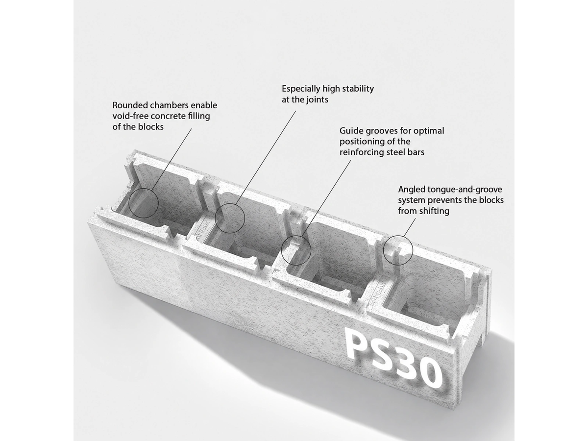
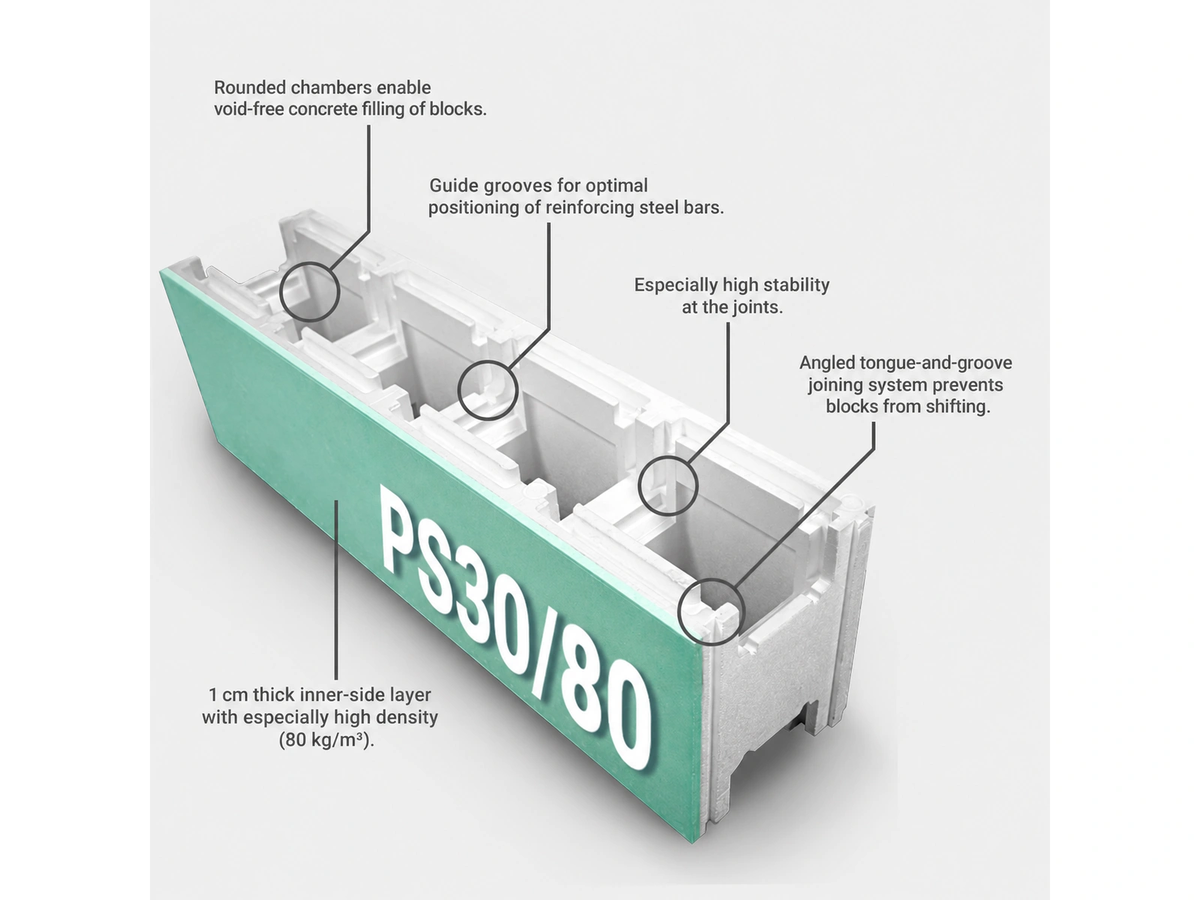
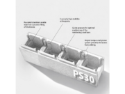
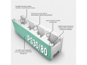
| Walls | 125 EPS blocks 100 × 25 × 30 cm (PS30 or combined 80/30) |
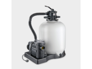
| Filtering | Poolsana sand filter unit with Speck pump |
| Installation | in-ground, on a reinforced concrete slab |
| Package | PROFI |
| Block | PS30, Combined 80/30 |
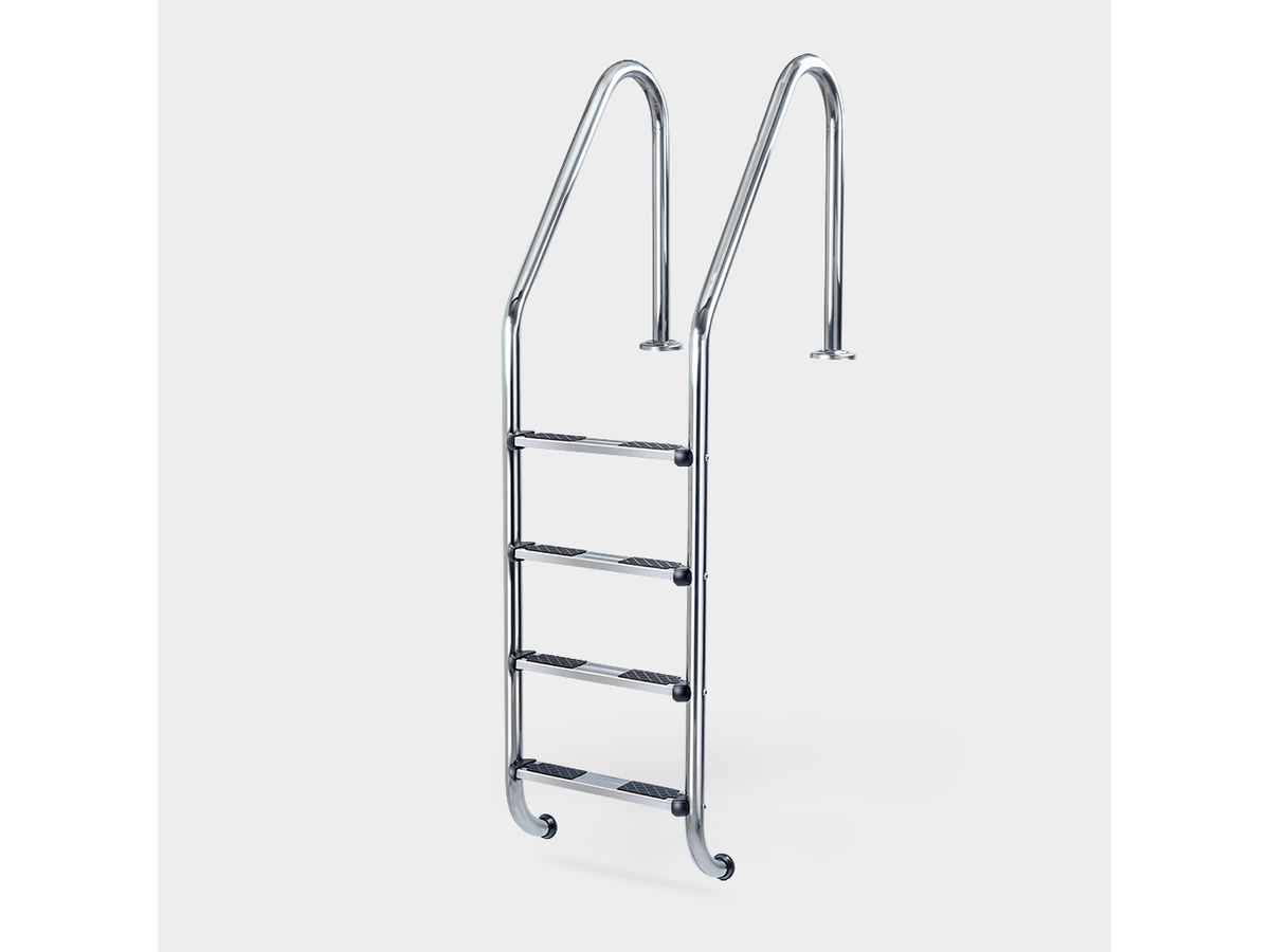
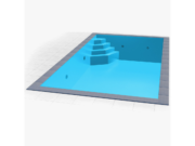
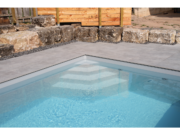
| Inlet | Ladder, Built-in corner steps |
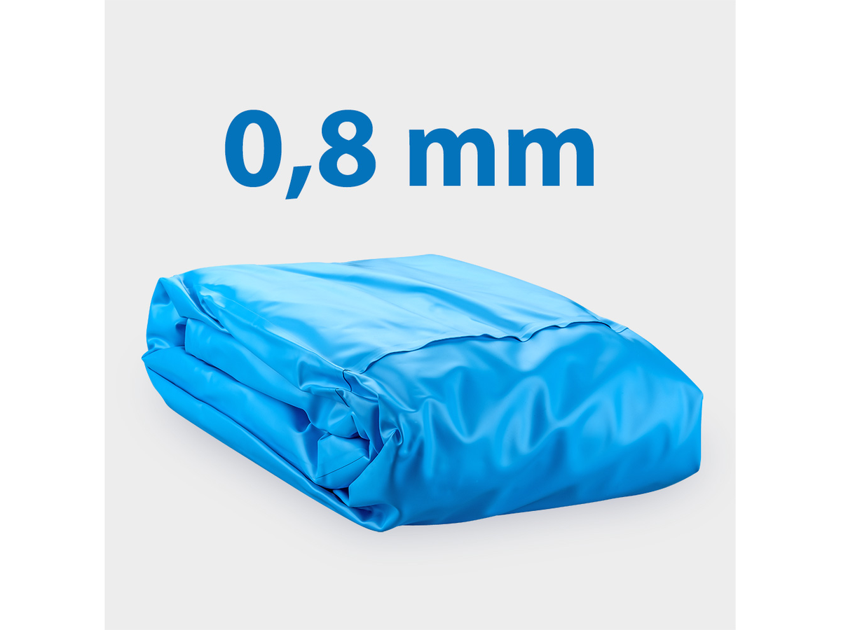
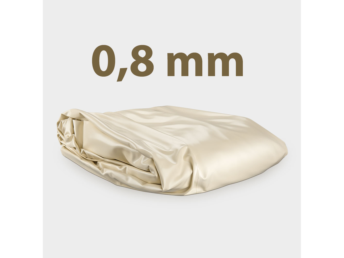
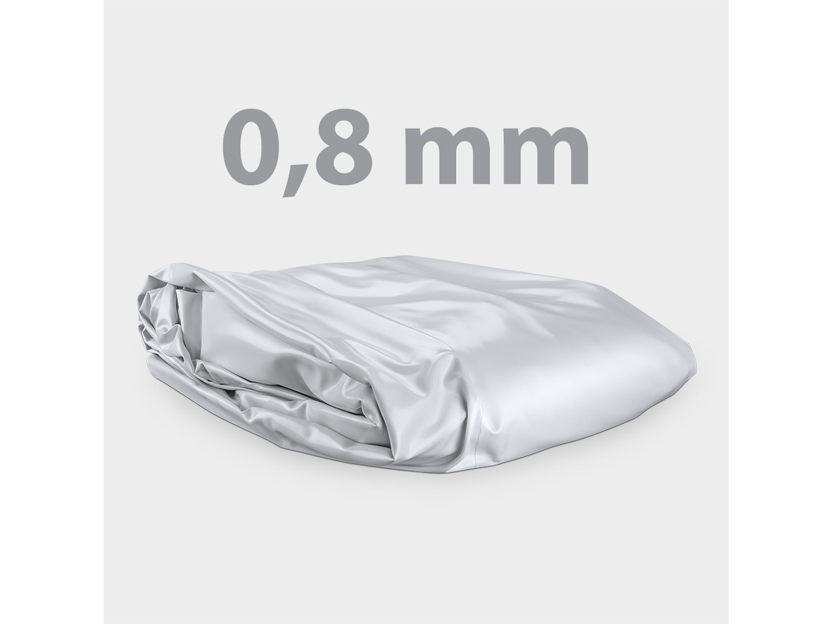
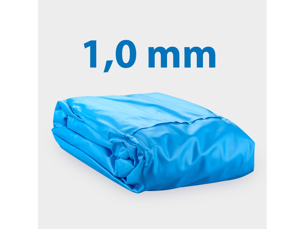
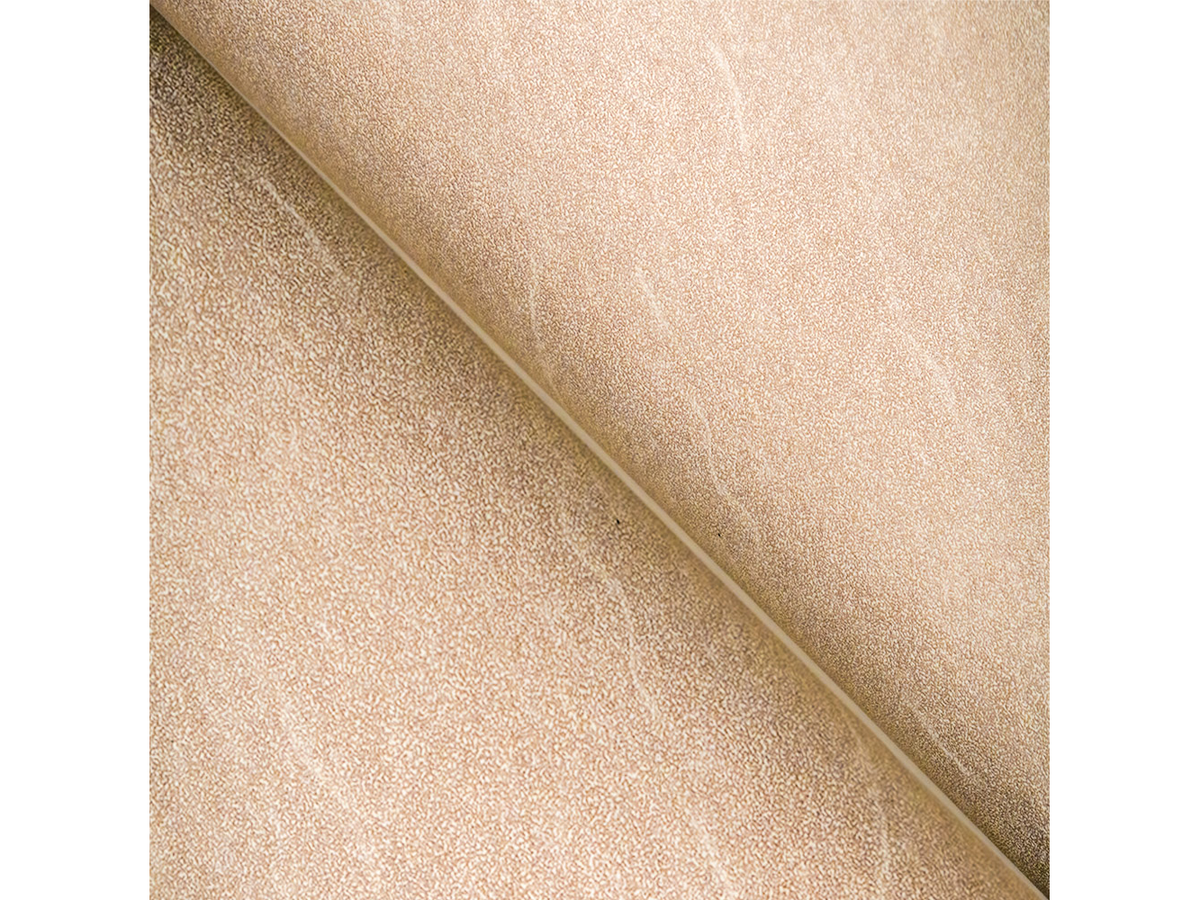
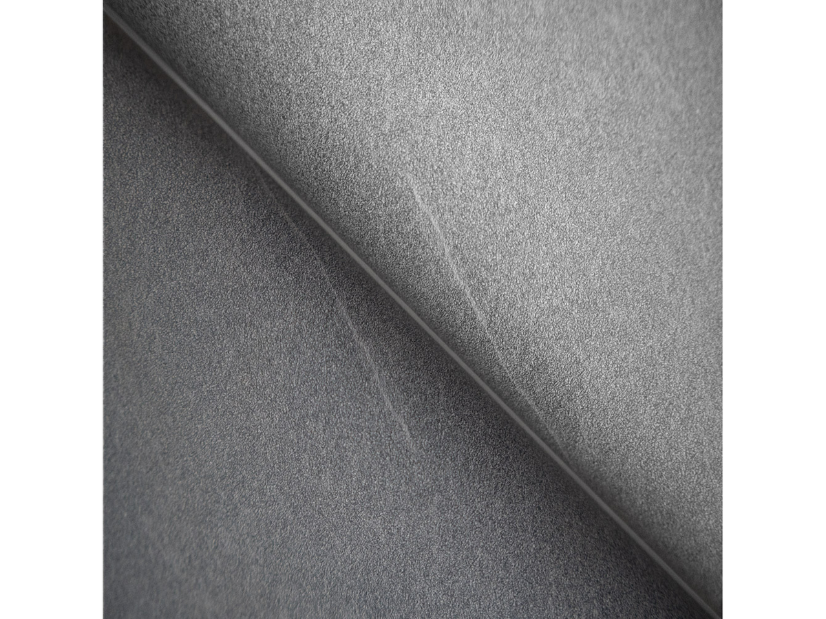
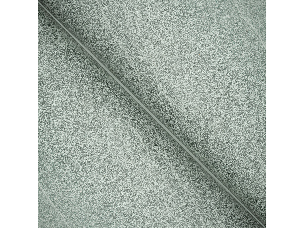
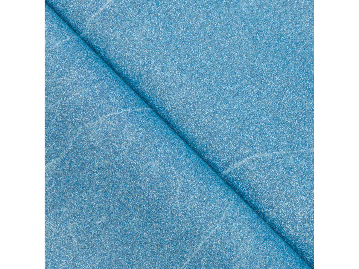
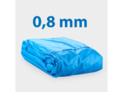
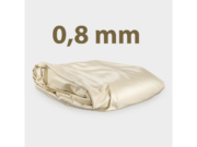
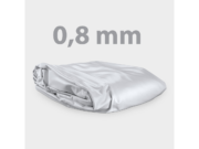
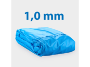
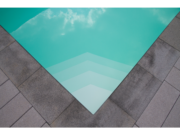
| Cladding | Blue 0.8 mm, Sand 0.8 mm, Grey 0.8 mm, Blue 1.0 mm, 4D sand 0.9 mm, 4D anthracite 0.9 mm, 4D green 0.9 mm, 4D blue 0.9 mm |
 Germany, Nuremberg · Exclusive representative
Poolsana – pools and equipment from Germany.
German specialist in swimming pools, saunas and accessories, founded in 2005 in Nuremberg.
in Nuremberg
A swimming pool for every home at a reasonable price
Poolsana was founded in 2005 in Nuremberg by a local pool and sauna construction company with many years of experience in the industry. Its goal is to make it possible for every property owner to afford their own pool or sauna.
Poolsana’s technical department checks the compatibility of pumps, sand filters and other components, and the warehouse of over 3000 m² guarantees fast delivery. At Baseini.NET we are the exclusive representative for Bulgaria.
The components in Poolsana kits are selected and tested to work together – no surprises during installation.
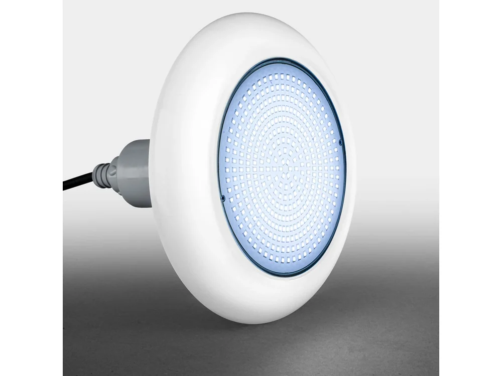
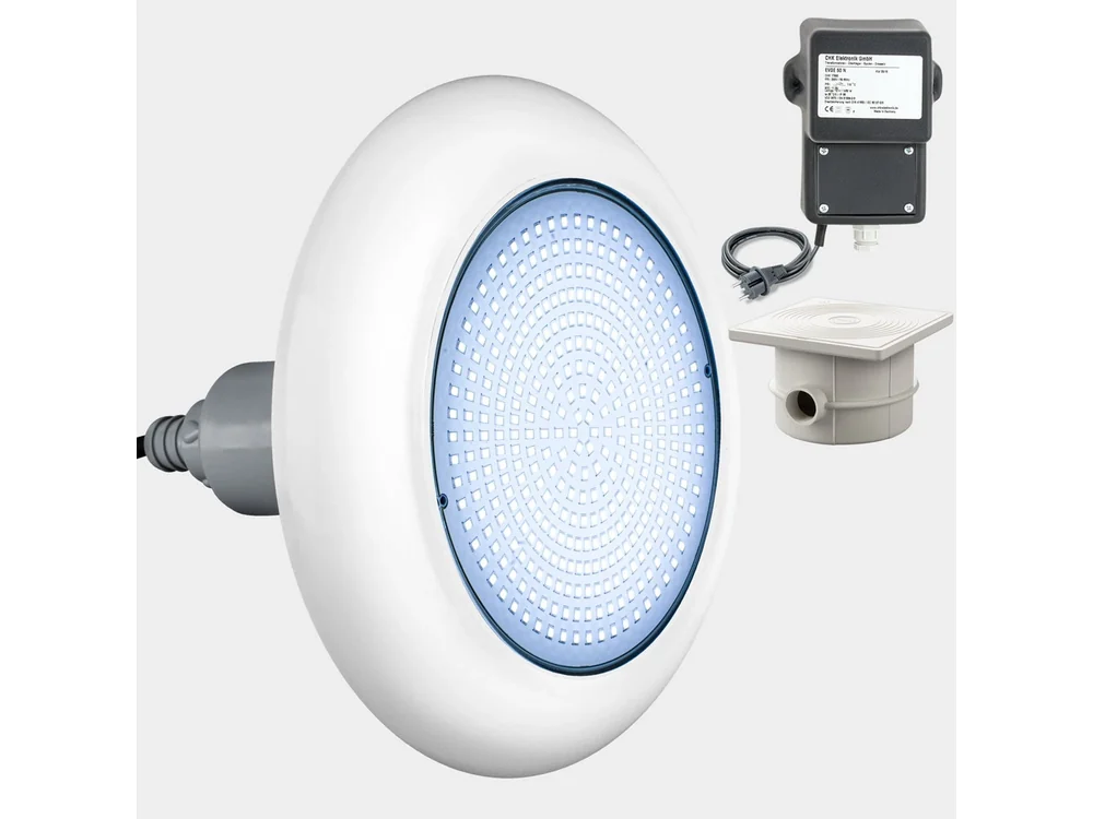
Poolsana products in our shop



Installing a rectangular polystyrene (EPS) pool – step by step
Here is the complete Poolsana manufacturer's manual for assembling and installing rectangular pools made of polystyrene (EPS) formwork blocks: from choosing the site and excavation through the floor slab, building and reinforcing the walls and filling them with concrete, to fitting the liner, backfilling and the safety instructions. At the end, the manual for the built-in corner steps Smart / Smaragd is also included. The steps are valid only for rectangular pools.
- 1 Introduction and important notes
- 2 Required materials
- 3 Choosing the location for the pool and the filtration system
- 4 Excavating the pool pit
- 5 Construction work
- 6 Installing the components
- 7 Filling the formwork blocks
- 8 Installing the hanging profile and the underlay
- 9 Installing the liner (film)
- 10 Installing the system components / final assembly
- 11 Backfilling the pool
- 12 Safety instructions
- 13 Built-in corner steps Smart / Smaragd (for sizes with corner steps)
Introduction and important notes
Here is the complete Poolsana manufacturer's manual for assembling and installing rectangular pools made of polystyrene (EPS) formwork blocks – from excavation and the floor slab through building and reinforcing the walls, filling with concrete and fitting the liner to backfilling and the safety instructions. The steps are valid only for rectangular pools. The images are illustrative and serve as a general visual aid.
Before installation, check your pool for completeness and all parts for perfect condition. No liability is accepted for transport damage reported on parts that have already been assembled.
The success of the construction project depends on the following points, described in detail below:
- material requirements;
- choosing the location and the filtration system;
- excavating the pool pit;
- building the foundation (floor) slab;
- installing the formwork blocks;
- installing the built-in components;
- filling the formwork blocks with concrete;
- installing the hanging profile;
- laying the non-woven underlay (geotextile);
- hanging the liner (film);
- flanging the built-in components;
- installing the pool pipes and the filtration system;
- backfilling the pool.
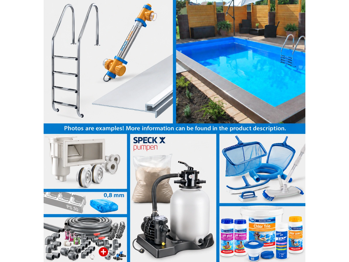
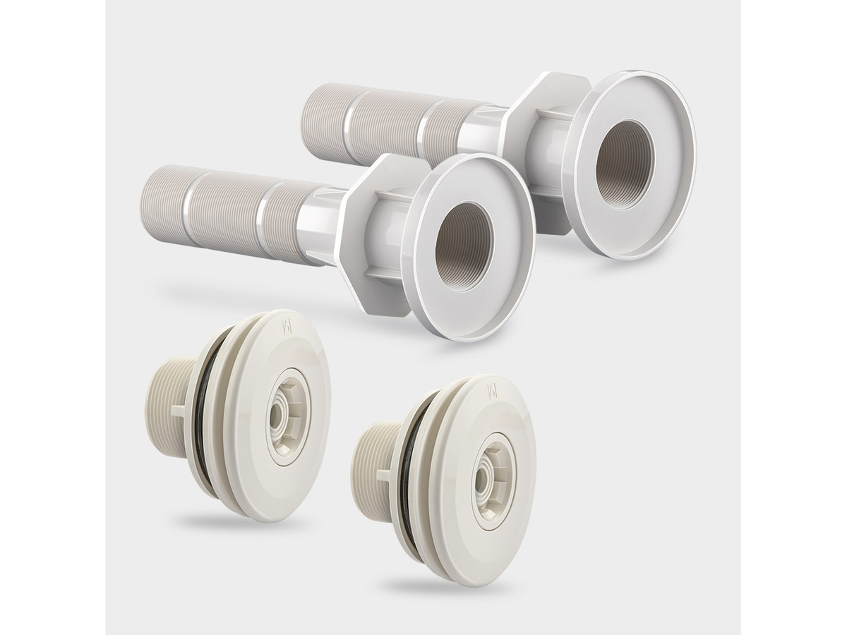
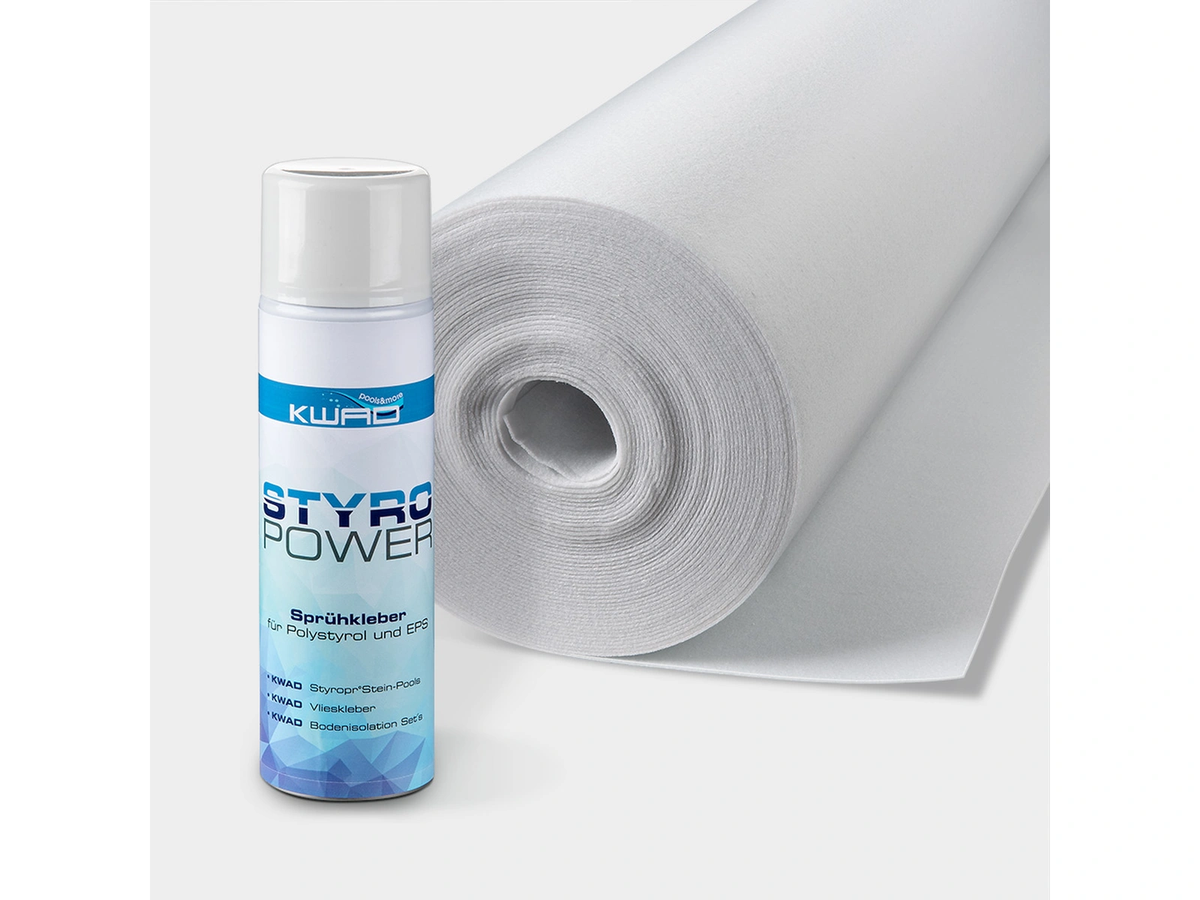
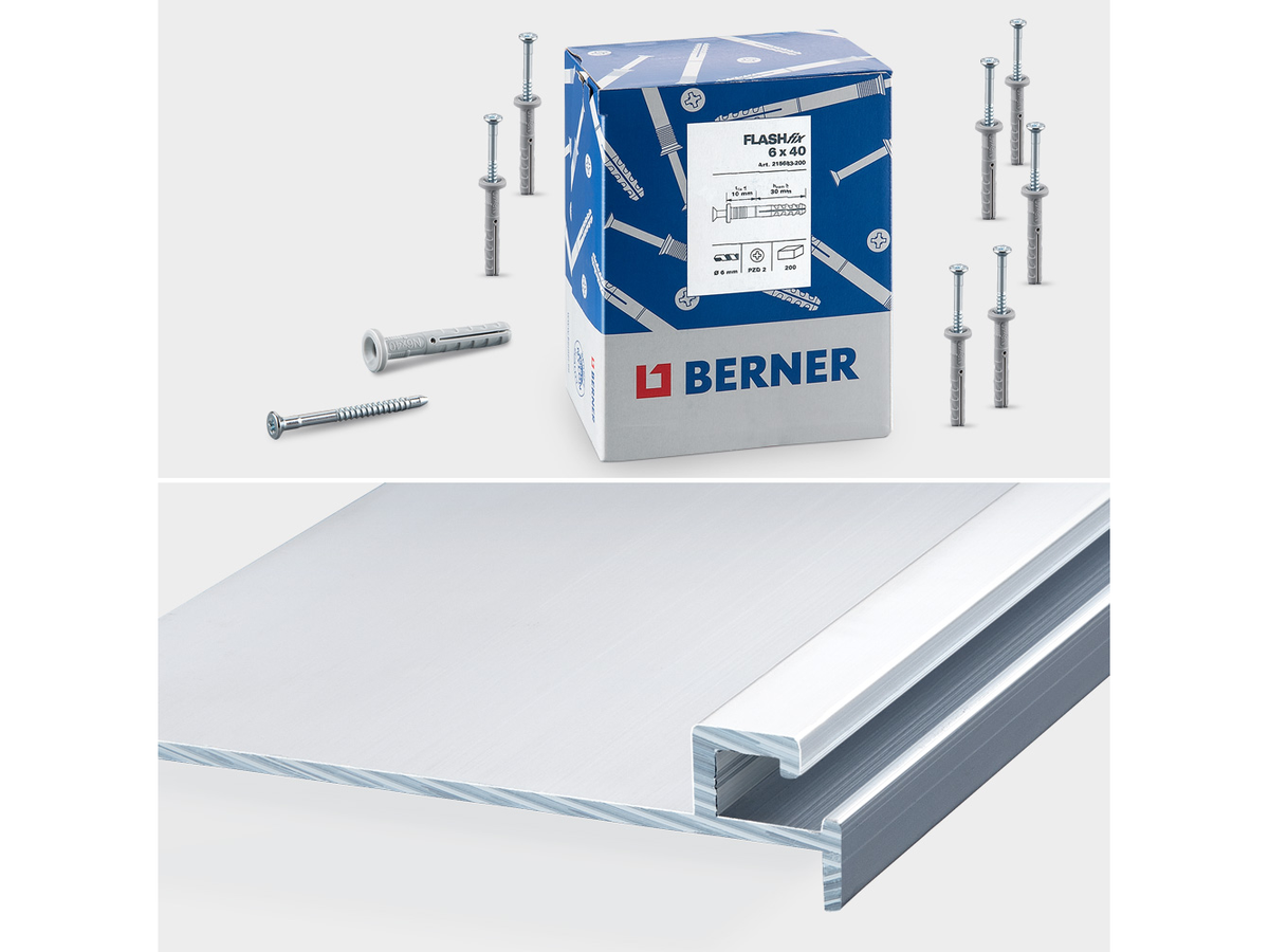
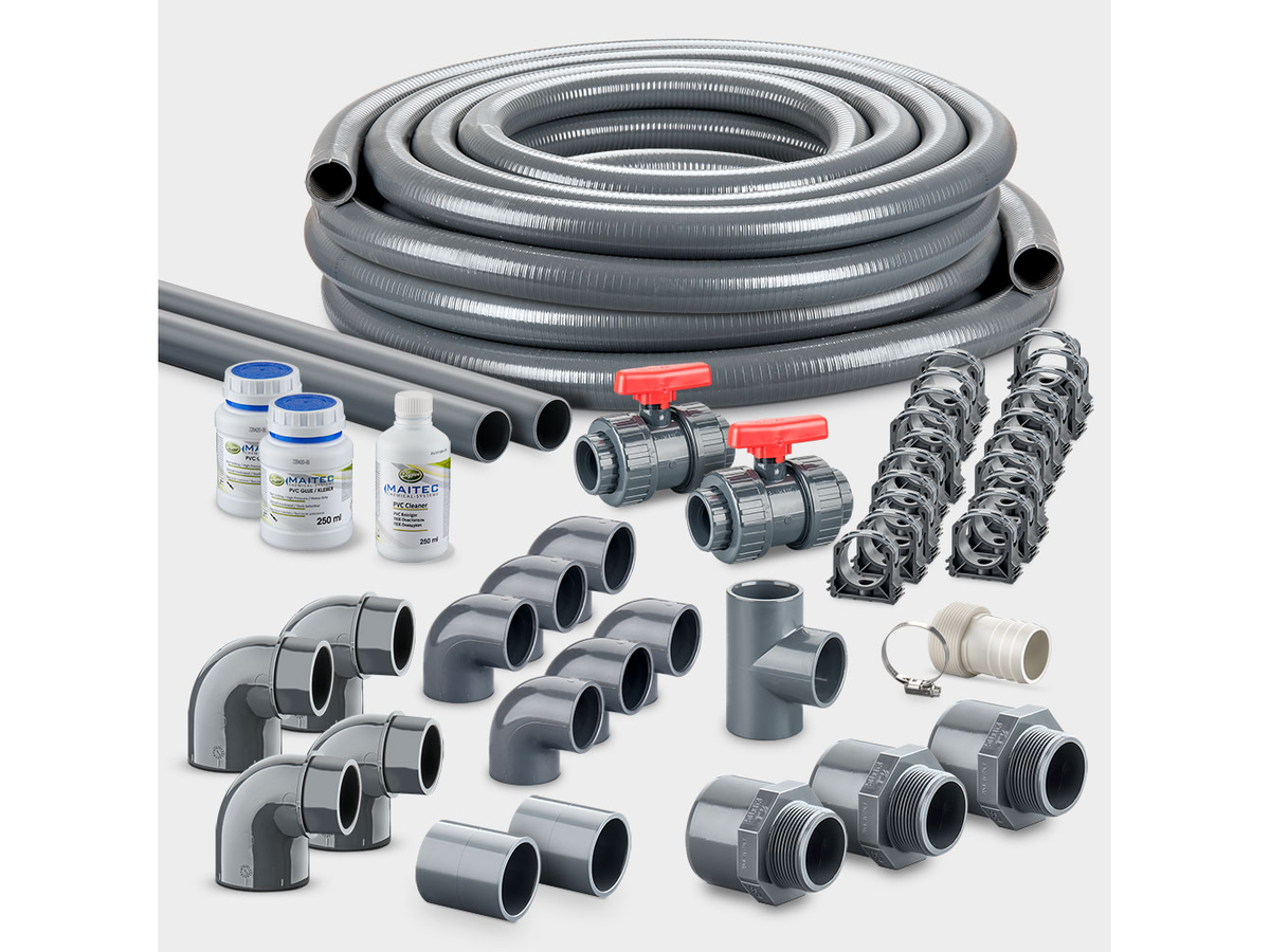
Note on the package: the package includes EPS blocks, a liner with a hanging edge, aluminium profiles, a skimmer (wide-mouth or Slim), a floor drain (only for PROFI High Level), 2 inlet nozzles, pipes, geotextile with spray adhesive, a filter, a ladder or corner steps. Technical shafts, underwater lights and counter-current systems are not part of the package – their descriptions below are for the cases where you decide to add them as options.
Required materials
Pool (without technical shaft)
Pool dimensions (length × width × depth): 5.00 × 3.00 × 1.50 m; 6.00 × 3.00 × 1.50 m; 7.00 × 3.50 × 1.50 m; 8.00 × 4.00 × 1.50 m. The quantities below are given by size, in the same order: 5×3 / 6×3 / 7×3.5 / 8×4 m.
- Formwork blocks (included in the delivery): 85 / 95 / 110 / 125 pcs
- End caps (end pieces, included in the set): in all sizes 20 upper and 20 lower sliders each
- Concrete slab (20 cm thick): approx. 4.5 / 5.5 / 7 / 9 m³
- Concrete for filling the wall: approx. 3.1 / 3.5 / 4 / 4.5 m³
- Reinforcing mesh Q257A: 41 / 48 / 63 / 80 m²
- U-shaped rebar 8 mm, 80 × 10 × 80 cm (edge of the floor slab): 64 / 72 / 84 / 96 pieces
- Corner brackets 12 mm, 65 × 46 cm (connecting reinforcement): 32 / 36 / 42 / 48 pcs
- Corner brackets 12 mm, 65 × 20 cm (joint reinforcement): 32 / 36 / 42 / 48 pcs
- Rebar 12 mm, 140 cm (vertical reinforcement of the hollow chambers): 72 / 80 / 92 / 104 pieces
- Rebar 6 mm (ring reinforcement): 20 pieces of 5 m and 20 pieces of 3 m (5×3); 20 of 6 m and 20 of 3 m (6×3); 20 of 7 m and 20 of 3.5 m (7×3.5); 20 of 8 m and 20 of 4 m (8×4)
- U-profile 6 mm, 60 × 10 × 60 cm (corner joint): 40 pcs in all sizes
- Rebar 12 mm (reinforcement for the top row of blocks): 8 pieces of 5 m and 8 of 3 m (5×3); 8 of 6 m and 8 of 3 m (6×3); 8 of 7 m and 8 of 3.5 m (7×3.5); 8 of 8 m and 8 of 4 m (8×4)
- U-shaped rebar 12 mm, 60 × 10 × 60 cm (corner joint, top row of blocks): 16 pieces in all sizes
- U-shaped rebar 6 mm, 20 × 10 × 20 cm (for connecting the top ring): 68 / 76 / 88 / 100 pieces
Technical shafts (optional – not included in the package)
If you add a technical shaft to the pool, additional materials are required.
Shaft 3.00 × 1.00 × 1.50 m:
- Formwork blocks: 28 pcs (plus additional sliders if needed)
- Concrete floor slab (20 cm): approx. 1 m³
- Concrete for filling the walls: approx. 1 m³
- Reinforcing mesh Q257A: 10 m²
- U-shaped rebar 8 mm, 80 × 10 × 80 cm (edge of the floor slab): 20 pcs
- Corner brackets 12 mm, 65 × 46 cm (connecting reinforcement): 10 pcs
- Corner brackets 12 mm, 65 × 20 cm (joint reinforcement): 10 pcs
- Rebar 12 mm, 140 cm (vertical reinforcement of the hollow chambers): 22 pcs
- Rebar 6 mm (ring reinforcement): 16 pcs of 1 m and 8 pcs of 3 m
- U-shaped rebar 6 mm, 60 × 10 × 60 cm (corner joint): 20 pcs
- Rebar 12 mm (ring reinforcement for the top row of blocks): 8 pieces of 1 m and 4 pieces of 3 m
- U-shaped rebar 12 mm, 60 × 10 × 60 cm (corner joint, top row): 8 pcs
Shaft 1.00 × 1.00 × 1.50 m:
- Formwork blocks: 18 pcs (plus additional sliders if needed)
- Concrete slab (20 cm): approx. 0.5 m³
- Concrete for filling the walls: approx. 0.7 m³
- Reinforcing mesh Q257A: 5 m²
- U-shaped rebar 8 mm, 80 × 10 × 80 cm (edge of the floor slab): 20 pcs
- Corner brackets 12 mm, 65 × 46 cm (connecting reinforcement): 10 pcs
- Corner brackets 12 mm, 65 × 20 cm (joint reinforcement): 10 pcs
- Rebar 12 mm, 140 cm (vertical reinforcement of the hollow chambers): 22 pcs
- Rebar 6 mm (ring reinforcement): 24 pcs of 1 m
- U-shaped rebar 6 mm, 60 × 10 × 60 cm (corner joint): 20 pcs
- Rebar 12 mm (ring reinforcement for the top row of blocks): 12 pcs of 1 m
- U-shaped rebar 12 mm, 60 × 10 × 60 cm (corner joint, top row): 8 pcs
Choosing the location for the pool and the filtration system
When choosing the location for the pool, keep the following in mind:
- The pool may only be installed on firm, natural ground and under no circumstances on filled ground.
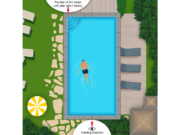
- The pool should be in a sunny spot, not far from the house. The skimmer should face the direction of the prevailing wind, so that dirt on the water surface is carried towards it. More importantly, however, the skimmer should be installed on the narrow side of the pool, closest to the filtration system.
- If a fence is planned around the pool, also take its position into account; if possible, the pool should not be directly in front of the living room window.
- Before digging the pit, draw the plan of the pool to better assess the final outer dimensions. The stated pool dimensions are internal – you need to add 2 × 25 cm to the length and to the width for the thickness of the walls.
- The ground must be professionally assessed to determine the appropriate thickness and quality of the concrete slab according to the condition of the terrain.
The construction instructions in this manual refer to the complete construction of the pool. If the pool is built on a slope, a retaining wall must be built on the slope side. Under no circumstances should the pool wall serve to support the slope. If in doubt, consult a construction specialist or structural engineer.
When choosing the location for the filtration system, observe the following:
- In general, the filtration system should be as close as possible to the pool, and it is preferable for the suction line (the line to the skimmer) to be shorter than the pressure line (the line to the nozzles).
- The system can be installed in a shaft, in the house or in a garden shed, etc. When installing in the house or in a shaft, make sure there is a floor drain for any leaking water. The backwash water must also be drained away – on average about 200 litres every 1–2 weeks. This can be done through a permanent connection to the sewer or, if necessary, through a hose directed to a suitable drain.
- If the filtration system is higher than the water level, the pump must be self-priming. Also observe the manufacturer's data on the maximum suction height.
- The planned heating method also affects the choice: with a solar system, the filtration system should be as close as possible to the solar collectors; with an air-to-water heat pump for outdoor installation, it is advisable for the filtration system to be in the garden as well; when connected to central heating via a heat exchanger, locating the filter in the house is almost unavoidable.
Excavating the pool pit
This type of pool is usually installed at ground level or at least slightly above it, so the excavation depth is calculated using the following example.
When determining the outer dimensions of the excavation pit, add to the stated pool dimensions the thickness of the polystyrene block walls (2 × 25 cm along the length and width), as well as about 60–70 cm of working space around the perimeter. Do not forget to leave enough room for a possible technical shaft for the equipment.
The excavation depth is the sum of the depth of the in-ground pool (150 cm), the concrete base (20 cm) and the cleaning layer – the sub-base (20 cm). In the example, the total excavation depth is 190 cm.
Example excavation dimensions for an 8 × 4 m pool together with a technical shaft (internal shaft dimensions 3 × 1 m): total excavation 4.0 × 5.7 m.
Construction work
Building the foundation slab
Before starting the floor slab, we recommend laying a base layer of 15–20 cm of crushed stone. This layer must be connected to a drainage system to carry away seepage water or runoff from the slope.
We then recommend building precise formwork for the slab. To determine the size of the concrete slab, add the wall thickness of 25 cm plus another 10 cm to the inner dimensions of the pool on each side.
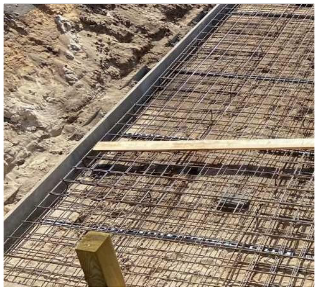
The floor slab is usually 20 cm thick and is reinforced with two layers of Q257A reinforcing mesh, with a concrete cover of 3 cm required (top and bottom). However, the exact thickness must be determined by a construction specialist according to the condition of the base.
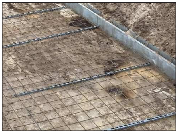
Then use a straight batten to level the filled formwork completely so that it is perfectly horizontal, and smooth the concrete surface.
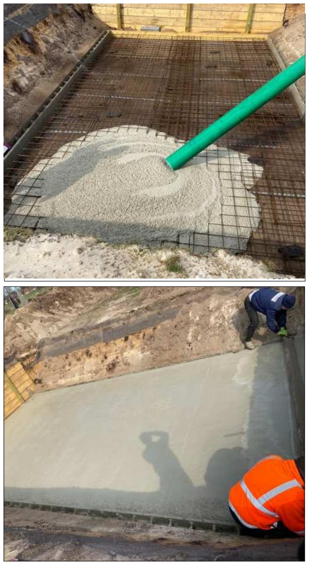
It is recommended to place a U-shaped iron bar measuring 20 × 4 × 20 cm at 75 cm intervals around the entire perimeter, with the open side facing the still-wet concrete, so that the first row of blocks can later be fixed with cable ties.
Connecting elements (corner brackets)
Connecting brackets 12 mm thick (dimensions 65 × 46 cm or 65 × 20 cm) are used to join the floor slab to the pool walls. Their anchoring ensures the connection between the slab and the walls.
Installing the corner brackets at a later stage makes levelling the concrete base easier. Once the base has been levelled, mark out the inner dimensions of the pool with a string. Then take a block as a template and press it into the still-wet concrete, starting from one corner. The remaining imprints will serve as a guide for installing the brackets.
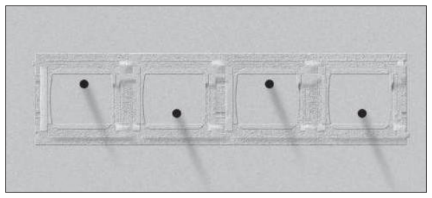
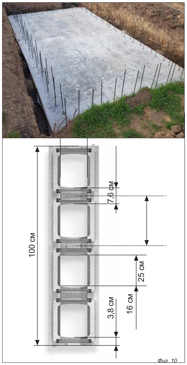
- The brackets are installed in a staggered pattern: the shorter bracket (65 × 20 cm) on the inner side of the pool, the longer one (65 × 46 cm) on the outer side.
- No brackets are placed in the corner chambers!
- Place the brackets at a slight angle so that they slide under the top layer of the reinforcing mesh.
- Once all the brackets are in place, smooth the surface of the first row of blocks again. The level base is the foundation for joint-free installation and a prerequisite for optimal liner installation without wrinkles.
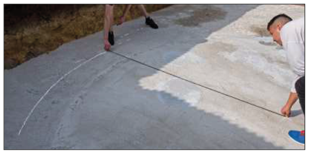
Installing the formwork blocks
Check the inner dimensions of the pool. The diagonals must always be of equal length. The blocks can then be fixed with cable ties to the U-shaped rods previously placed in the floor slab. For greater security, the blocks can also be tied to each other with cable ties.
The pool walls are usually built as a combination of corner and bonded joints or offset joints (the rows are staggered). Here too, some blocks will need to be adapted or cut to size.
Each row must include a double ring reinforcement of 6 mm rebar rods, as well as two U-profiles 60 × 10 × 60 cm in the corners. Place the ring reinforcement in the recesses provided for it in the blocks.
Measure the outer dimensions of the pool. Place two 6 mm rebar rods around the perimeter of the base (peripheral reinforcement). The ends of the rods must overlap by at least 30 cm (the two ends can be joined with cable ties or similar). The corner joints are made with two U-profiles 60 × 10 × 60 cm, also from 6 mm rebar.
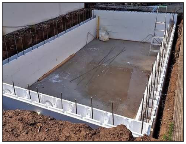
Place the first row of formwork blocks onto the connecting rebar rods protruding from the floor slab. If necessary, a block is cut to size – there are cutting marks every 25 cm for this purpose. The corners are formed with two formwork blocks joined at their ends. The side protrusion of one block is cut off so that no joint is formed. Both corner blocks must be cut on the underside so that the reinforcement can be laid correctly and the concrete can later flow freely around the corner. Use the caps from the set to close the block that remains open on the outer side.
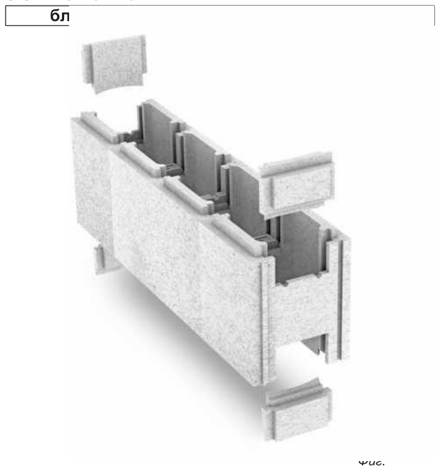
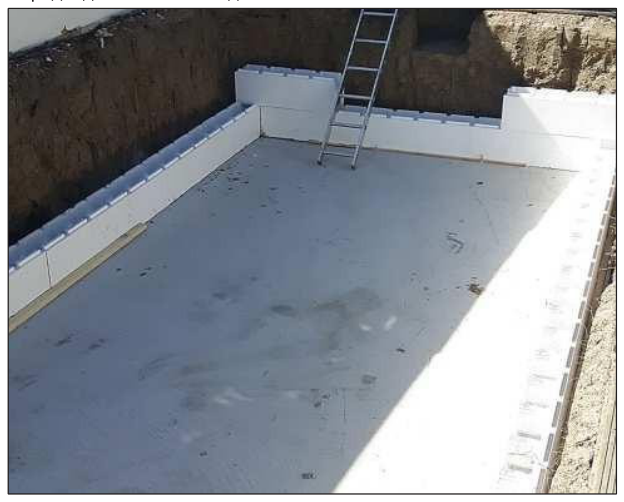
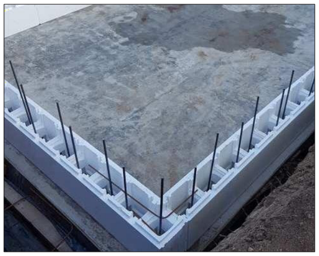
Each chamber is provided with vertical reinforcement of 1 rebar rod of 12 mm with a height of about 1.40 m (at a pool depth of 1.20 m this corresponds to a height of 1.10 m), alternating inner and outer offsets so that they match the connecting reinforcement. The steel rods are tied to the peripheral ring reinforcement with cable ties. The corners are reinforced with 2 pieces of 12 mm rebar each.
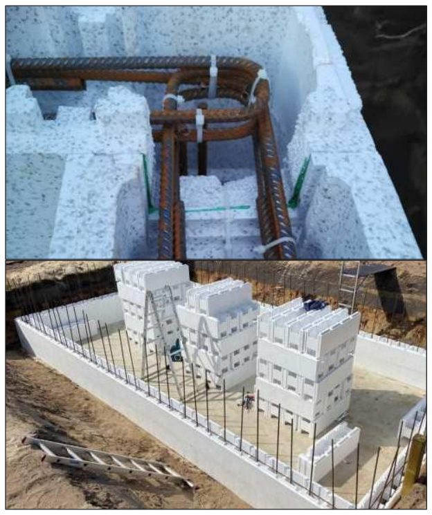
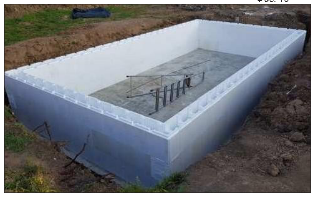
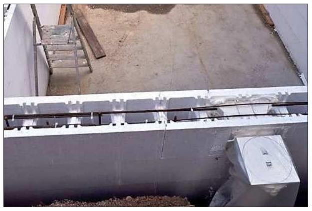
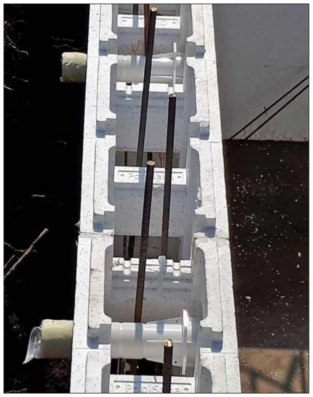
Example of a pool project with internal dimensions of 5.00 × 3.00 m:
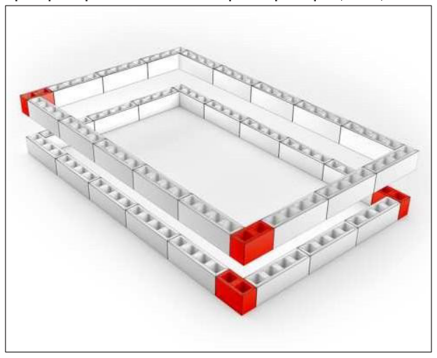
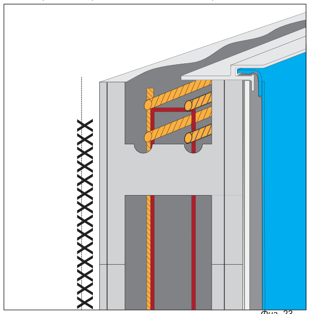
Top row of blocks: build a support surface for the two upper iron bars. The top row is reinforced with a 4-bar ring reinforcement cage of 12 mm rebar. The horizontal U-profiles (60 × 10 × 60 cm) in this row are also 12 mm thick and are used four per corner. The U-shaped bars 6 mm (20 × 10 × 20 cm) are fixed to the vertical reinforcement, among other ways, with cable ties. In addition, the upper edge of the polystyrene block is cut with a utility knife to create a flat surface for the later installation of the suspension profile.
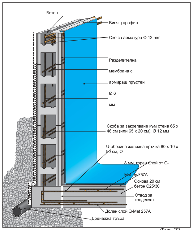
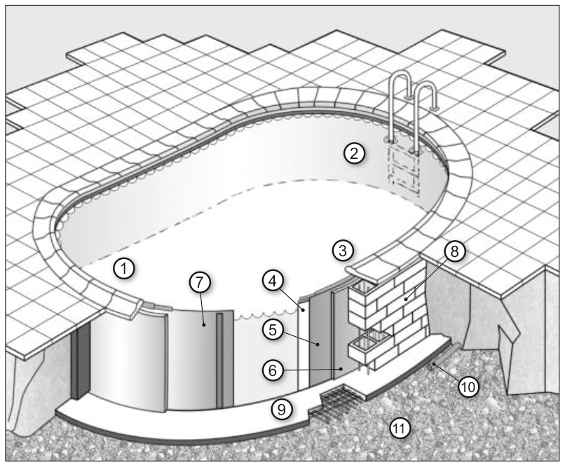
The cross-section drawing (fig. 22) shows: concrete, suspension profile, reinforcement eyelet Ø 12 mm, separating membrane (geotextile) with reinforcing ring Ø 6 mm, wall fixing bracket 65 × 46 cm (or 65 × 20 cm) Ø 12 mm, U-shaped iron bar 80 × 10 × 80 cm Ø 8 mm, upper layer of reinforcing mesh Q257A, 20 cm base of C25/30 concrete, condensate drain, lower layer of Q257A mesh and drainage pipe.
Example of installing a pool 3.00 m wide with an adjoining technical shaft of 1.00 × 1.00 m (optional) – rows 1 and 2:
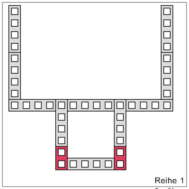
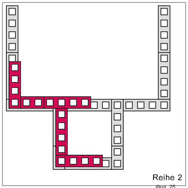
Installing the components
The following are required for installing the components: a circular saw, a hole saw, a hand saw, a sharp knife, gas-free quick-drying construction foam and a tape measure. Also follow the installation instructions supplied with each component!
Component layout:
Skimmer and nozzles
View from the skimmer side (for pools 600 × 300, 700 × 350 and 800 × 400 cm):
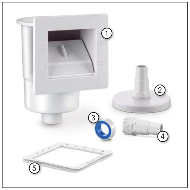
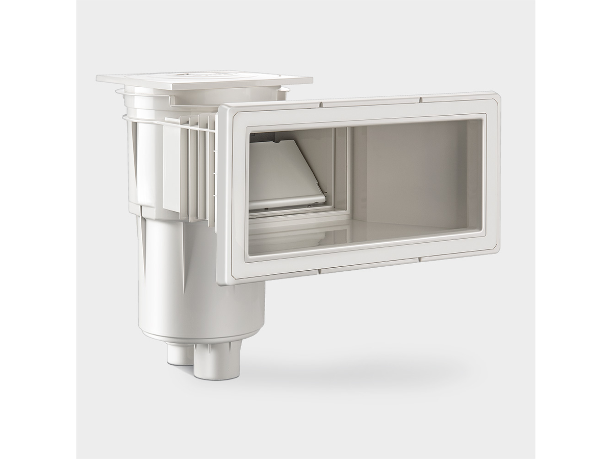
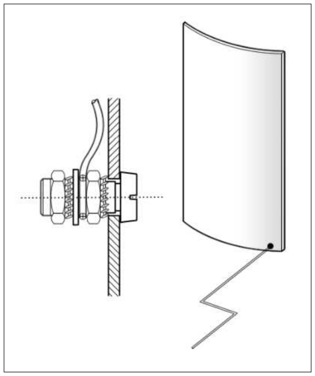
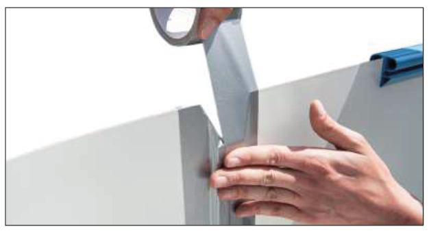
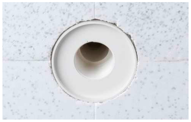
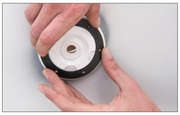
Cut the corresponding recess for the skimmer in the formwork block and position the skimmer so that the flange frame is flush with the finished wall. The skimmer can then be fixed with construction foam. Keep the threaded sleeves clean by covering them with tape.
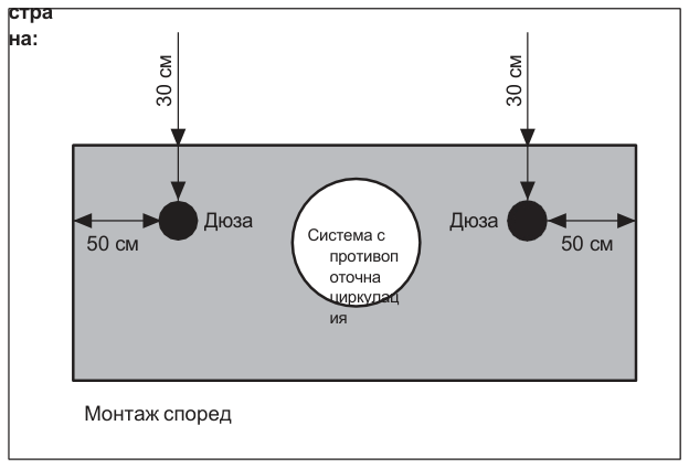
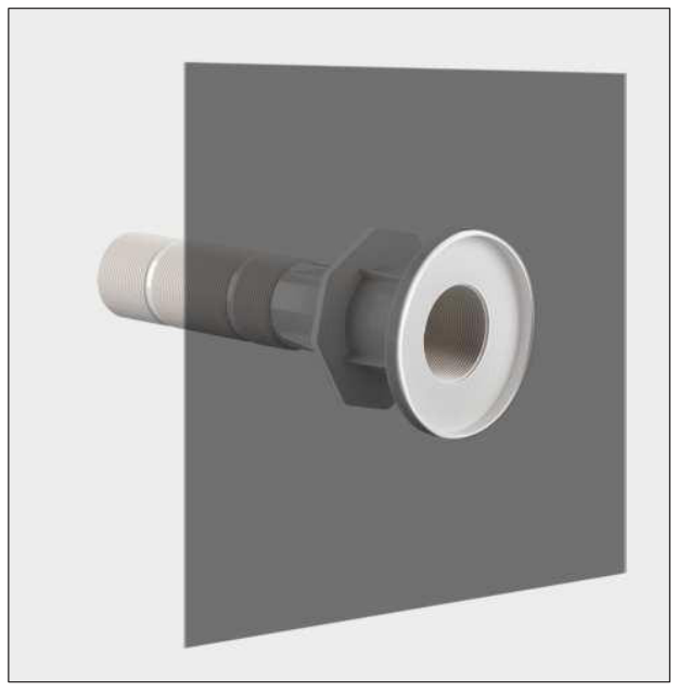
View of the nozzle: the position of the two inlet nozzles (30 cm from the top edge, 50 cm from the side ends of the side) and – optionally – of the counter-current system is shown in fig. 29.
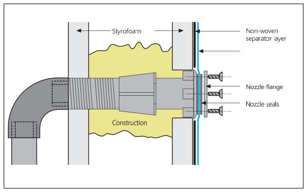
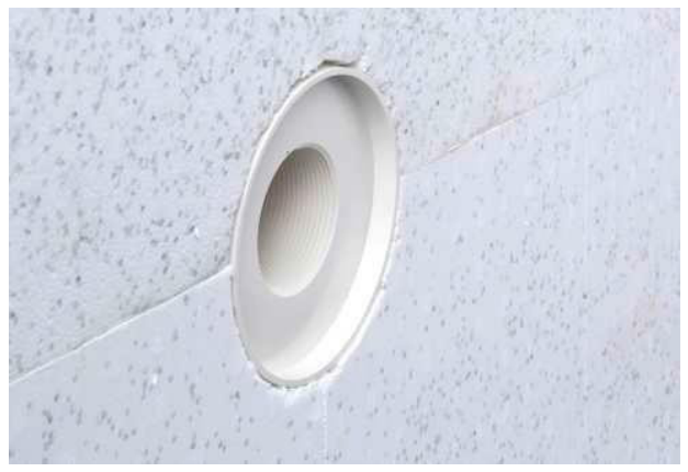
The walls of the sleeves must also be installed so that they fit snugly against the inner side of the formwork block.
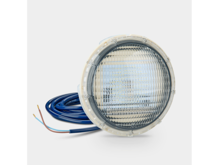
Underwater lights (optional – not included in the package)
View from the light side – the position with two lights is shown in fig. 34.
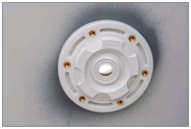
If only one light is used, it must be centred both vertically and horizontally in the masonry (the centre of the width and the centre of the height of the pool).
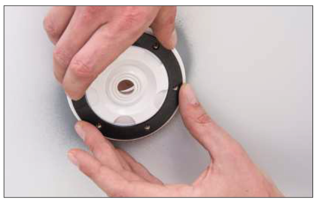
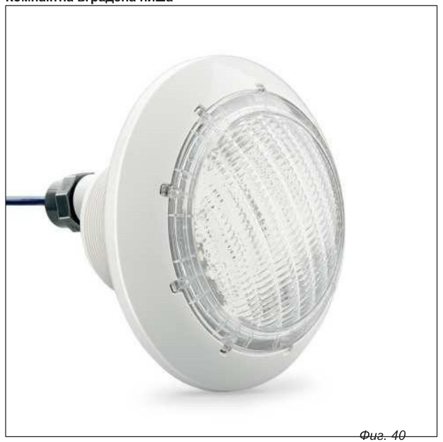
Types of lights: PAR56 – standard built-in niche; compact light – compact built-in niche.
Standard PAR56 built-in niche: use one of the two included sealing strips to outline the installation recess, and cut a recess into the formwork block. When installing the recess, it is important – even if there is an inward-protruding edge – that the recess frame is mounted flush with the wall.
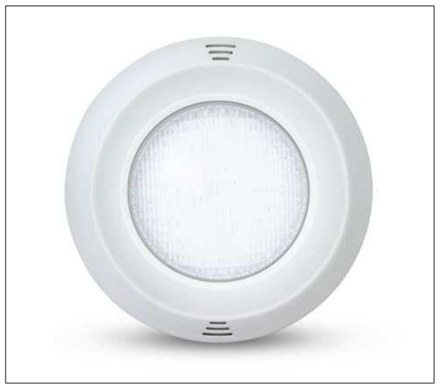
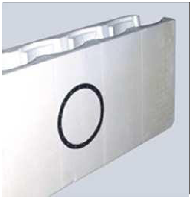
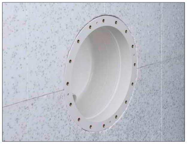
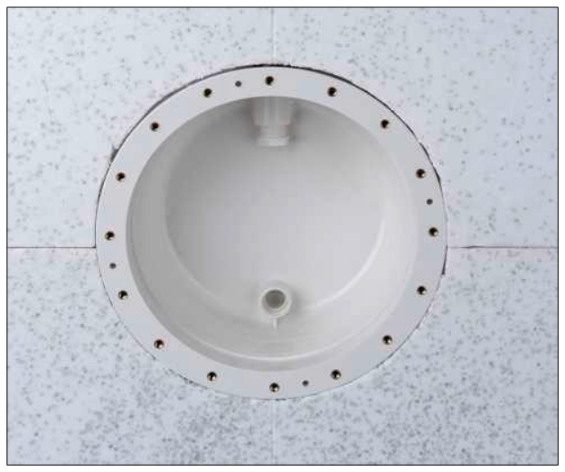
Compact built-in niche: with the compact light, the recess is inserted directly in the same way as with the standard recessed PAR56 housing. Here too, the flange frame must be flush with the formwork block.
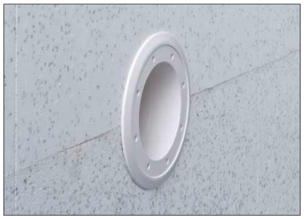
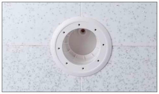
Alternatively, the lock nut can be extended with a pipe section with a diameter of 125 mm, and this entire assembly inserted into the pool wall. The built-in housing itself is then simply screwed into the lock nut.
Filling the formwork blocks
The rows of formwork blocks are usually filled in three layers from all sides. Under no circumstances should the filling be done entirely from one side only.
- Pumping the concrete must be carried out by an experienced specialist company. In all cases, the use of a fall-arrest device (extension hose of the concrete pump) is mandatory.
- It is recommended to tie the rows of blocks together horizontally and vertically with cable ties before filling, so that the blocks do not lift and no voids form. Manual filling is also possible.
- Use C25/30 concrete to fill the formwork blocks.
- To avoid voids in the concrete, compact it carefully with a tamping rod.
Installing the hanging profile and the underlay
Installing the hanging profile
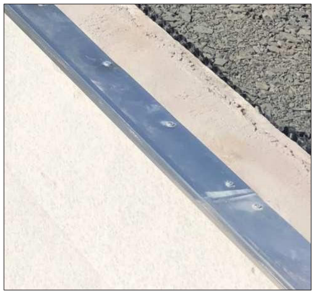
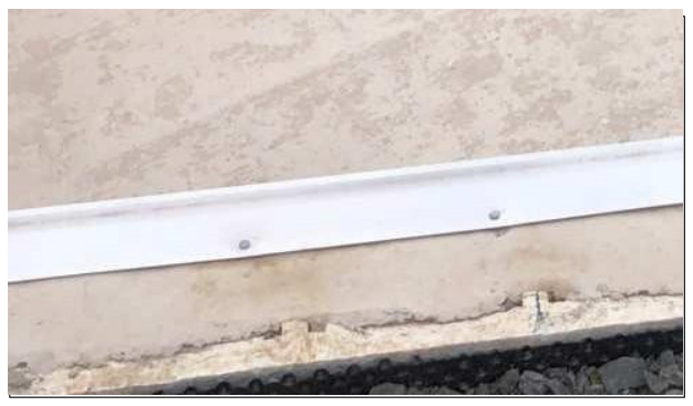
When installing the liner fixing profile, make sure the profile lies snugly against the inner side of the pool. All concrete splashes must be removed to prevent any unevenness.
The profile strip is fixed to the top of the formwork blocks with drive-in anchors about every 25 cm. Make sure the strips are fixed perfectly straight along the entire length and width.
Installing the hanging profile at the corners
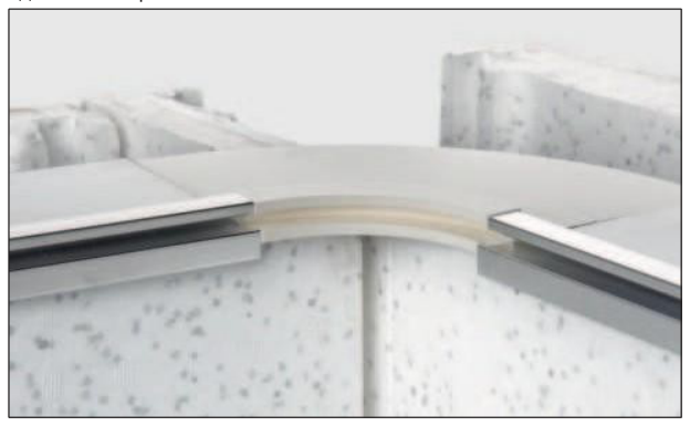
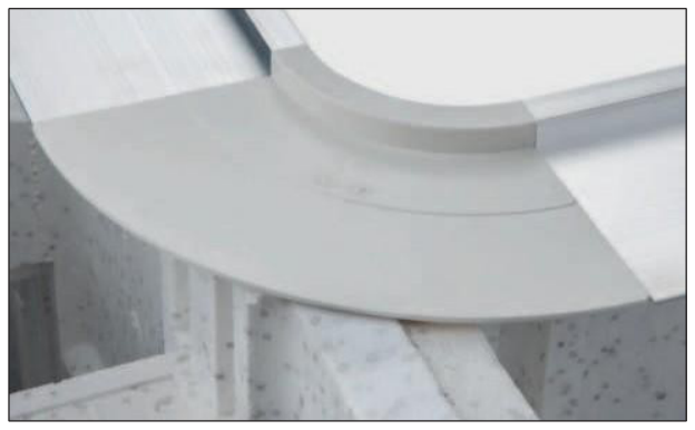
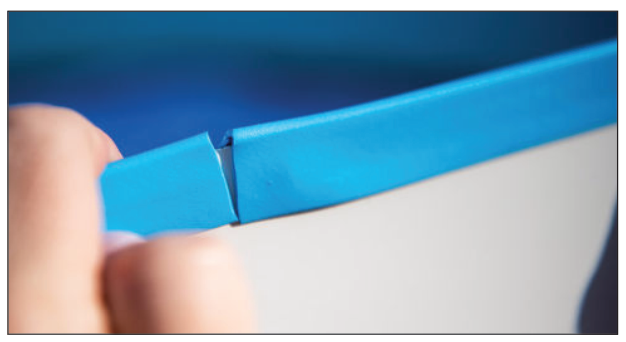
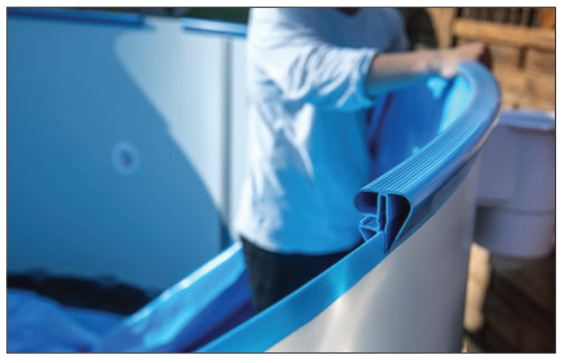
Depending on the type of liner, plastic profiles that are used in the four corners may be included in the set. If included, the supplied quarter-circle plastic corner profiles must be fitted in every corner of the pool so that the liner is held firmly along its entire length. If necessary, the length of the straight suspension rails is adjusted to leave enough room for the rounded corner profiles. The corner profiles must be aligned so that their front ends are flush with the straight suspension profiles.
If the plastic profiles are not included, only straight suspension profiles are used, which are not mitred but joined to each other at the corners (corner joint).
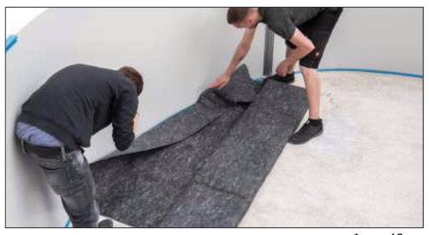
Laying the non-woven underlay (geotextile)
Also check that no voids or cracks have formed between the polystyrene blocks when filling them with concrete. If so, fill them and use mesh fabric.
The non-woven underlay prevents direct contact between the pool liner and the polystyrene, since otherwise the polystyrene would extract the plasticiser from the PVC liner.
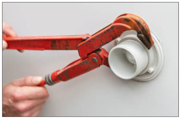
Before fitting the geotextile, screw the inlet nozzles into the openings in the wall. Seal the outer thread of the nozzle body with PTFE tape and screw it, together with the gasket, into the wall opening (without screw holes) until the flange frame is flush with the surface of the pool wall. Remove the adjusting ring and the nozzle eyeball – they are refitted together with the cover after flanging.
The geotextile is available in different widths (1.5 m or 2.0 m). It is best to start laying from the pool walls.
- Rolls 1.5 m wide: installation is horizontal along the wall. The entire wall height can be covered with one roll. The excess beyond the width of the sheet is laid towards the floor slab. When laying the underlay on the floor, the excess from the wall is left as a double layer under the floor underlay. Use spray adhesive to fix the underlay to the walls at certain points.
- Rolls 2.0 m wide: the underlay is laid vertically along the wall. Cut the geotextile so that it is about 5 cm longer than the wall. When laying it on the floor, the excess material is left in place to form a double layer. Use spray adhesive to fix the geotextile to the walls at certain points.
The underlay can also be fixed to the floor at certain points with spray adhesive. Make sure, however, that the strips are joined at the edges (not overlapping).
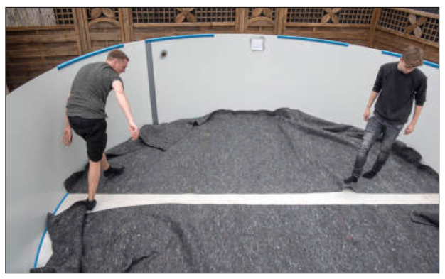
Once the geotextile is fully stretched out, it is cut tightly around the built-in components. Do not stretch the geotextile! Then fit a gasket on the flange frame of the skimmer, the inlet nozzles and – if present – the underwater light.

Installing the liner (film)
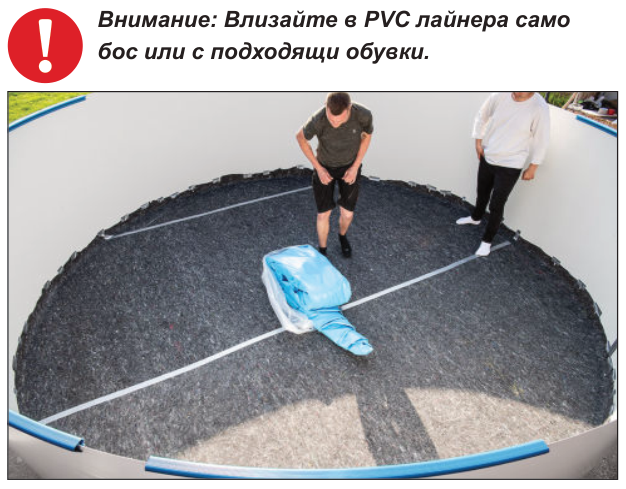
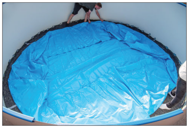
To compensate for the expansion caused by temperature and water pressure, the liner is manufactured slightly smaller than the pool. Therefore, place the liner in the centre of the pool and spread it out so that the welded seams on the floor are equidistant from the corners.
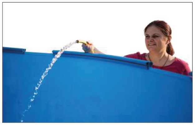
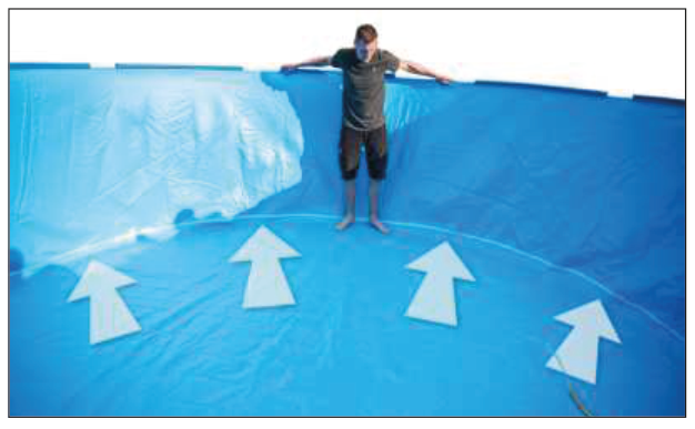
Hang the liner in the middle of each side in the suspension profile, so that it is fixed crosswise about one metre into the profile on each side. Then the film is fixed completely on each side, starting from the middle. Any diagonal wrinkles can be smoothed out by gently stretching the film in the same direction.
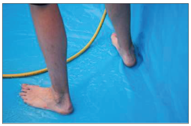
Then smooth out the wrinkles from the floor towards the pool wall. Above all, make sure that the liner seam where the floor and walls meet lies exactly in the corner where the pool wall joins the floor. The liner must fit snugly everywhere before the pool is filled and have as few wrinkles as possible. Any remaining stubborn wrinkles can be corrected by filling the pool with about 3–5 cm of water and pushing the wrinkles outwards.
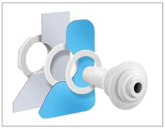
Installing the system components / final assembly
When the water level is approximately 20 cm below the first component, flanging can begin. The following instructions apply only to our components!
Inlet nozzles: once the film is aligned, pre-drill the screw holes, for example with an awl. Glue the gasket behind the flange so that it sits between the film and the flange. Tighten the flange screws crosswise. Then cut the film along the opening. Finally, screw the ball and the adjusting ring back on and fit the cover.
Skimmer: drill the screw holes, glue the gasket behind the flange and tighten the screws crosswise; then cut out the opening for the skimmer and fit the cover. Fit the skimmer flap and the filter basket.
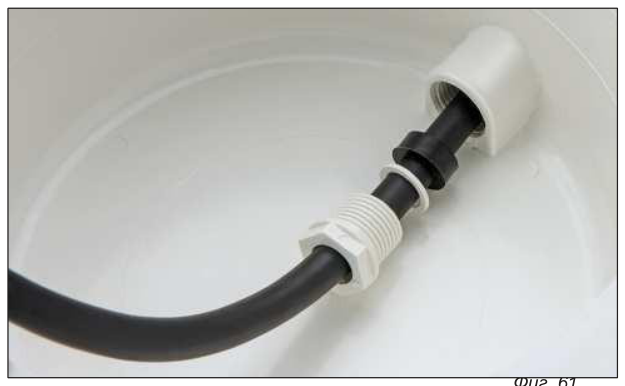
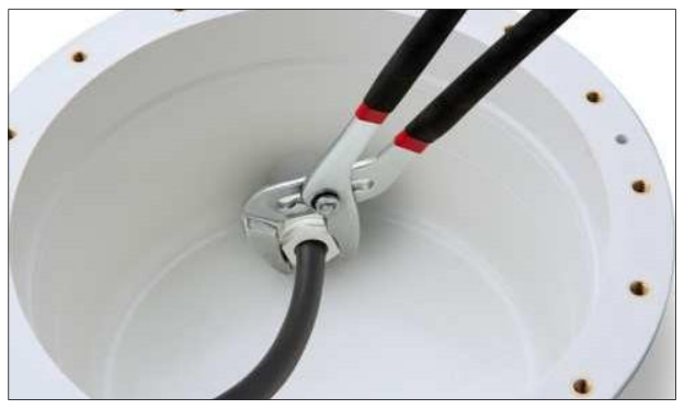
PAR56 light (optional – not included in the package): here too, the screw holes are drilled first. Then a gasket is glued behind the flange and the flange is screwed down crosswise. Finally, the opening for the light is cut out. Unscrew the nut of the cable gland at the top of the installation niche, slide the gland along the cable (use lubricant if needed and pull the cable at an angle) and route the light's cable from the inside out to the cable gland. The remaining cable must be long enough for the lamp to be pulled above the water level for replacement when the pool is full. Tighten the cable gland again, coil the cable around the light, slide the light into the niche and secure it with fixing screws if necessary. Finally, glue the last sealing washer onto the flange with the bolts and fit the remaining parts. Follow the installation instructions supplied with the light.
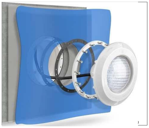
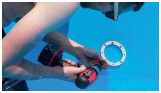
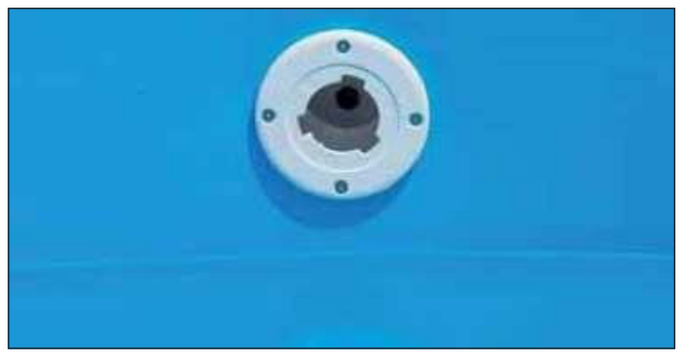
Compact light (optional – not included in the package): glue a hole gasket onto the smooth rear side of the flange. Then position the flange, drill the screw holes through the film with an awl or similar tool and tighten the flange crosswise. Now you can carefully cut out the opening with a utility knife.
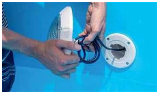
Pool piping and filtration systems: see the detailed piping instructions and the installation manual with the corresponding piping diagram.
Backfilling the pool
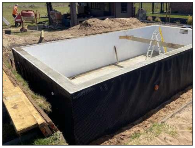
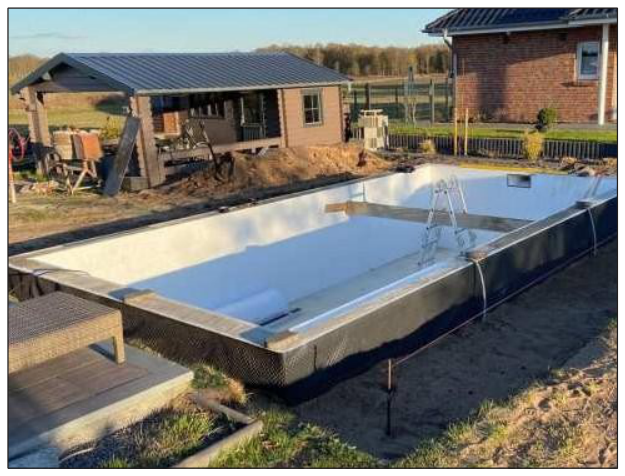
You can start backfilling the pool once the concrete has dried (approximately 3–4 weeks). The most suitable backfill material is rounded gravel or frost-resistant gravel.
- When backfilling, make sure the laid pipes are not damaged or crushed by stones. Therefore, lay the pipes on a layer of sand and cover them with sand. The soil around the pipes must not be compacted mechanically.
- To protect the polystyrene blocks, you can apply a waterproofing layer (bitumen or dimpled membrane) to the outer wall of the pool.
General notes
- This manual is based on the manufacturer's practical experience and current technical knowledge. It can serve only as a general guide, as the manufacturer has no influence over the specific conditions at the site.
- If components from other manufacturers are installed (e.g. Roman steps, lights, counter-current systems), also follow their respective installation instructions.
- All electrical connections must be carried out by a licensed electrician.
- Use only standard pool chemicals available in well-stocked hardware or specialist shops, and dose them only according to the instructions.
- When starting the filtration system for the first time, check the system and piping for leaks.
- When preparing the filtration system for winter, always follow the manufacturer's instructions.
Safety instructions
First aid in a water incident: pull the casualty out immediately. Check the pulse and breathing. If necessary, immediately perform mouth-to-mouth resuscitation and chest compressions. Notify the emergency services.
Please read all the information carefully before using the pool, and ask if anything is unclear. The instructions have been prepared to ensure your safety and that of the other users. Keep this document in a safe place. The typical risks of using the pool are described below, without the list being exhaustive – use common sense in all activities around and in the pool.
Safety of persons who cannot swim:
- Always make sure that non-swimmers and users with limited swimming skills – especially small children – are supervised by a person who can rescue them and call for help in an emergency.
- Appoint a person capable of providing help to watch the pool at all times while it is in use.
- Non-swimmers and people with limited swimming skills must wear personal protective equipment (e.g. inflatable armbands) when using the pool.
- Remove toys from the pool and the area around it when the pool is not in use or not being supervised, so that they do not attract children.
Safe access to the pool: if the means of access (the ladder) cannot be raised or folded so that children cannot unexpectedly gain access and drown, we recommend securing access to the pool with a safety device.
Safety devices: they not only prevent children from unexpectedly getting into the pool, but also protect against unauthorized access in general. Therefore, do not neglect safety accessories. Depending on the circumstances, these may be a fence, a cover with special safety features, a pool enclosure or an alarm system. We recommend also securing the doors and windows of the house, as well as the entrance to the property.
Safety equipment: we recommend keeping rescue equipment (e.g. a lifebuoy) near the pool. Make sure there is a working telephone nearby and a list of emergency numbers, so that help can be called quickly.
Safe use of the pool:
- Encourage all users – especially children – to learn to swim.
- Learn to give first aid (cardiopulmonary resuscitation) and refresh your skills regularly.
- Before using the pool, explain to all users, including children, what to do in an emergency.
- Never jump into deep water – this can lead to serious injury or death.
- Do not use the pool under the influence of alcohol or medication that may affect your ability to use it safely.
- If the pool is equipped with a cover, make sure before use that the cover is fully raised or completely removed from the water surface.
- To protect users from waterborne diseases, make sure the water is always treated and kept in a hygienically safe condition. Familiarise yourself with the water treatment instructions in the user manual.
- Keep chemicals and water treatment products (for treatment, cleaning or disinfection) out of the reach of children.
- Folding ladders must be placed on a level surface.
- Place warning signs in a clearly visible location up to 2 metres from the pool.
Built-in corner steps Smart / Smaragd (for sizes with corner steps)
Manufacturer's instructions from TREND POOL for the built-in corner steps Underliner Stairs Smart and Smaragd. The steps are installed under the liner. For additional information or advice on filters, water care and accessories, as well as when ordering spare parts, please contact your distributor – state the date of purchase and the exact product description. As part of continuous technical development, the manufacturer reserves the right to make changes that improve the product.
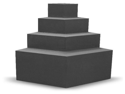
Completeness of delivery: check the contents for completeness against the parts list. In case of discrepancies, contact your distributor immediately. Before starting installation, read these instructions carefully and follow them.
Preparation: check that the supplied inner liner matches the desired position of the step. The position cannot be changed later.
Installation materials: elastic construction adhesive for stairs on a polystyrene base (not included), item no. 78205. 2 cartridges are needed for each element. It is applied with a sealant gun provided by the customer. Skin formation time (23 °C): about 10 minutes. Curing speed (23 °C): about 3 mm per 24 hours.
Step 1. Place the staircase in the designated corner and mark its exact position on the pool wall and floor. For multi-part staircases, position the lower section first. Then remove the staircase again. The cavity in the staircase is due to manufacturing reasons and is not grounds for a complaint.

Step 2. First apply the adhesive to the pool wall: (1) outline a contour 2 cm from the edge, viewed from the inside; (2) then fill the surface with adhesive in a wavy (curved) pattern. Then apply the adhesive to the pool floor: (3) a frame 2 cm from the edge, viewed from the inside; (4) a surface with a curved (wavy) pattern.
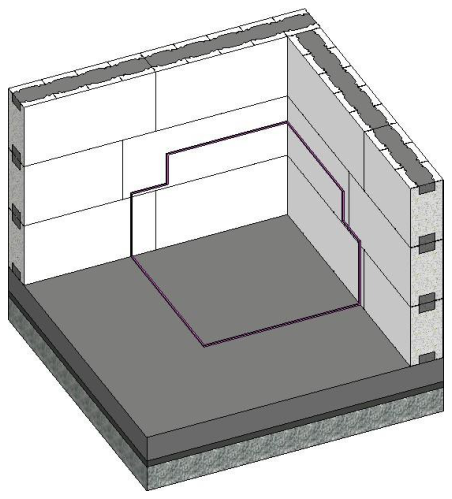
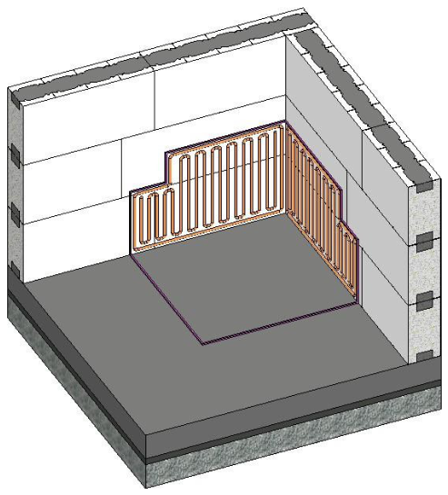
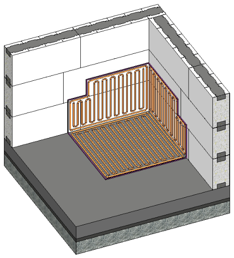
Step 3. Press the step onto the place where the adhesive has been applied. For multi-part steps, glue the lower part first.
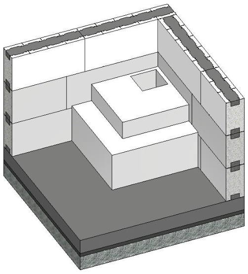
Step 4. For multi-part stairs, repeat steps 1–3. The upper half of the staircase is positioned on the lower half, marked, glued and fixed.
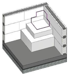 Step 4 – marking
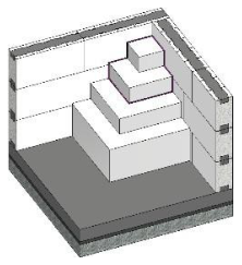 Step 4 – upper part
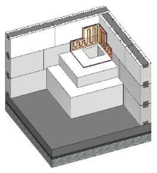 Step 4 – adhesive on the wall
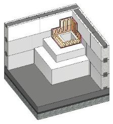 Step 4 – adhesive on the step
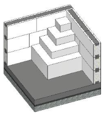 Step 4 – finished
Specific to Variofit and the adapter modules (only if they are part of your set):
- Step 1: first assemble the Variofit corner staircase as described in steps 1–3.
- Step 2: the Variofit adapter modules can then be installed in the same way (steps 1–3). Before that, however, they must be placed on the already installed corner staircase and marked.
- Step 3: if the adapter modules span the full width of the pool, first fix the steps in one corner and one of the adapter modules in the opposite corner. Finally, fix the middle adapter module.